You are using an out of date browser. It may not display this or other websites correctly.
You should upgrade or use an alternative browser.
You should upgrade or use an alternative browser.
Bandsaw cut out switch wiring
- Thread starter scottmk1
- Start date
scottmk1
Forum Supporter
- Messages
- 2,000
- Location
- Scotland
Ok, I've changed the black wire from the limit switch to match @carbon 's amended drawing, and replaced the fuse he mentions with a 3A spade connector type as I dont have any of the original ones (it was 2A) and as soon as I turn the main switch on the fuse blows. I have also bridged the 3 indicator lamps to complete that part of the circuit too.
carbon
Member
- Messages
- 2,897
- Location
- S. Glos. U.K
The switch top left turns power on to the saw, transformer is live.
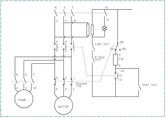
Pushing the start button connects power from terminal 13 on contactor to terminal B. Once contactor pulls in power then flows through the contacts between terminals 13 & 14 to B holding the contactor in.
Pushing either the emergency stop button or the limit switch breaks the circuit stopping the saw.
Also main motor overload will break the circuit in an overload event.
As the coolant pump is connected after the contactor it can only be on when the saw is running.
rtbcomp
Moderator
- Messages
- 18,574
- Location
- Sheffield UK
This is how it should be - but I don't think this tallies with the last wiring diagram. I haven't put the other bits of the circuit in yet, but this should get it going. I don't see the point of using the NN contacts on the main switch to switch the indicator bulb on the transformer secondary.

PS I'm going cross-eyed so E&OE

PS I'm going cross-eyed so E&OE
WorkshopChris
Member
- Messages
- 5,049
- Location
- South East Essex
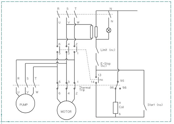
Isn't that the same as is now as it powers when start is pushed then hold in until E stop or limit brakes?13 14 needs to be below the b on the coil


