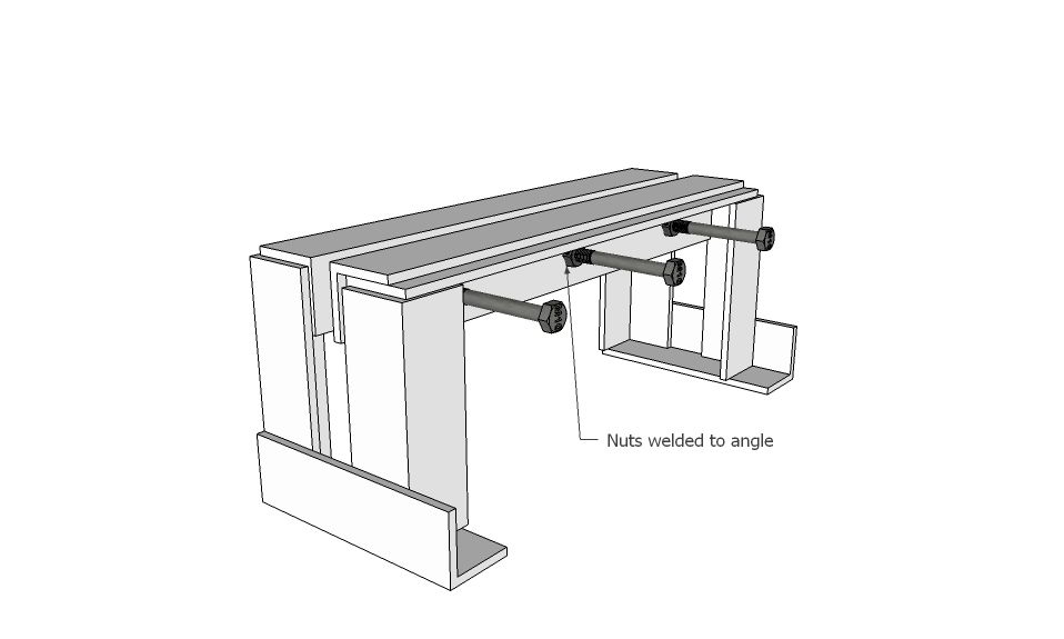
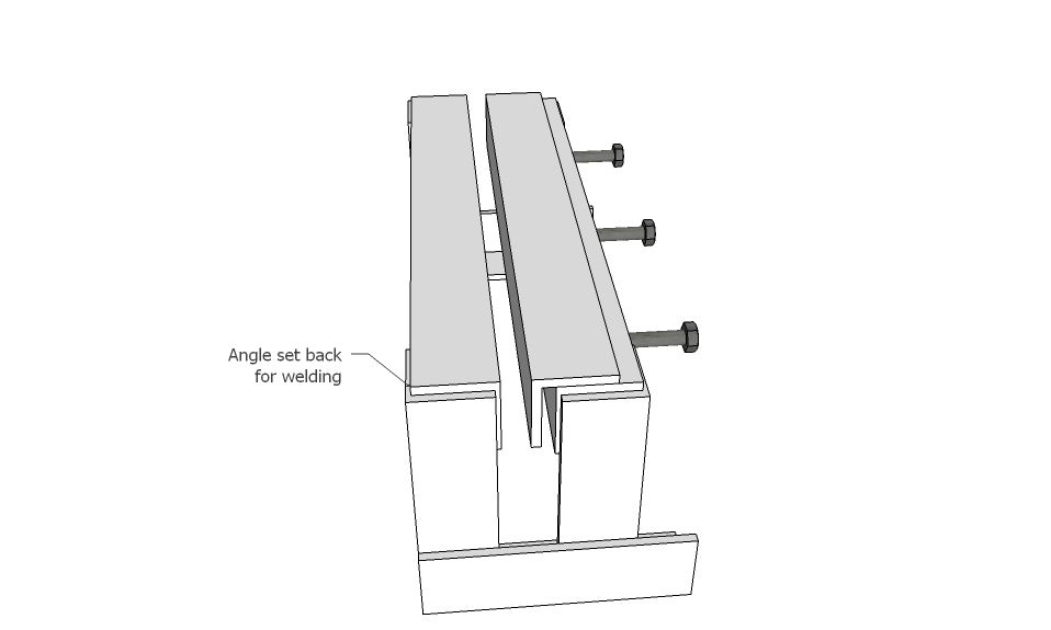
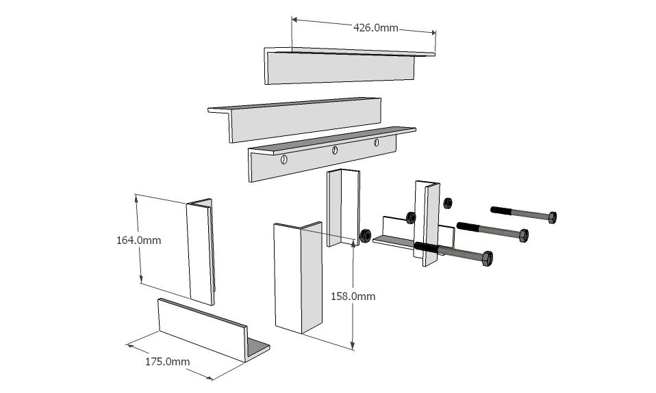
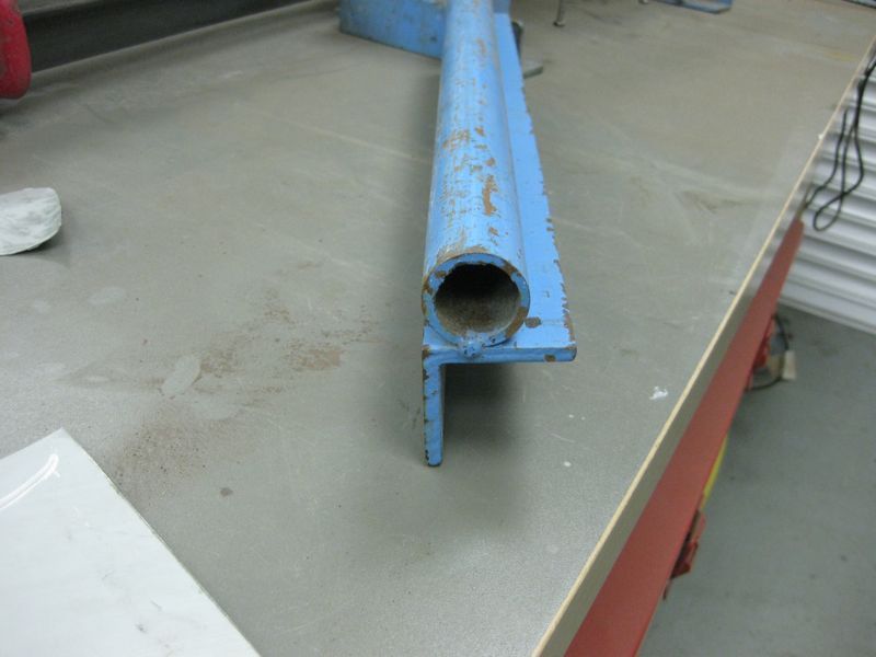
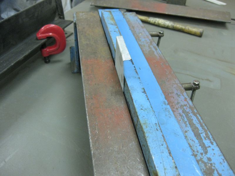
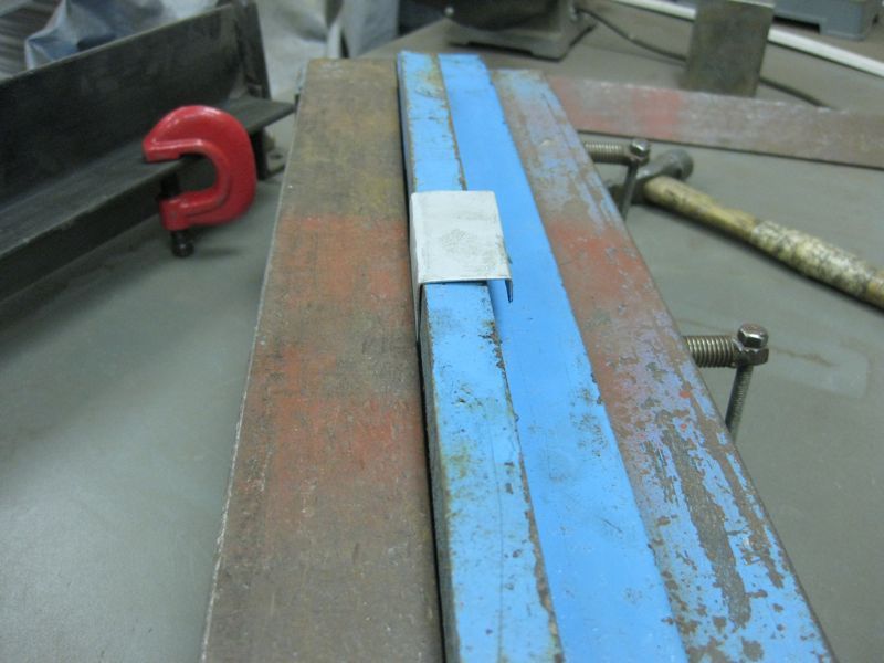
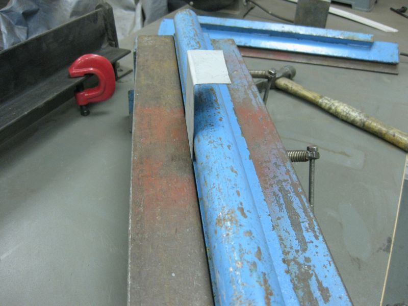
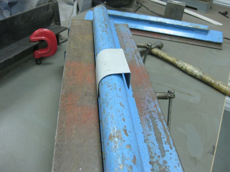
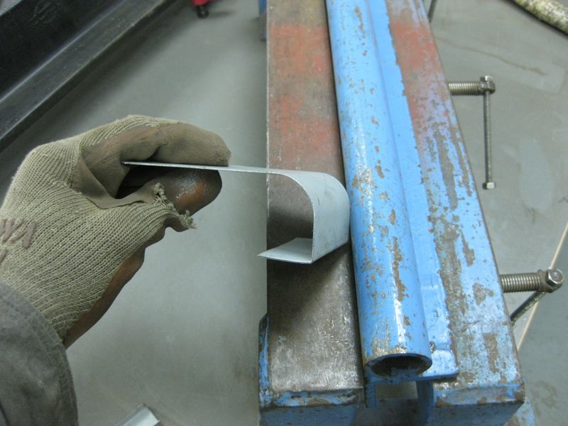
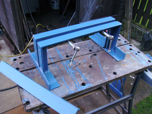
Today i have made myself a simple bender, i copied the design from a picture in a restoration thread on the RetroRides forum .
Its simple as its just a vice type grip, aimed at making floor to sill , chassis pieces etc , clamp the sheet in and bash it about a bit.
It isnt made to any particular plan , just sized to suit the materials i had at hand, which were 2 peices of 1.5" x 1.5" x 1/4" angle 32" long
and a length of 2" x 1.5" x 3/16" approx.
Now the hard part, as my only means of cutting the material to size is my cheap hacksaw that always tries to cut on the slant , and
a wobbly B&D workmate.
First i got the 2 lengths of 1.5" angle , marked them off square 7" in from each end then marked the 45deg angles, i cut the triangle
peices first and snapped them out with mole grips then cut them off square at the 7" mark, not ideal but easy to face up with the grinder.
That gave me 4 uprights at 7" and the horizontal peices at about 18"
Next i cut the 2 x 1.5" , 2 peices at 11" long to use as the base and a peice at 18" to "float" int the jaw.
Bloody arms were aching by now....
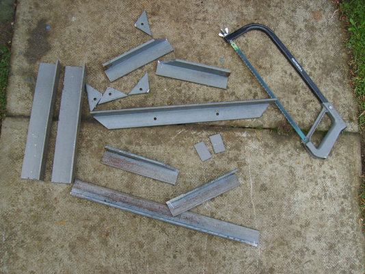
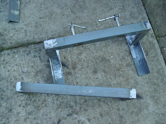
Firstly made up 2 "C" shapes from the 1.5" angle bits, i left about 1/8" gap on the joints to help me get my dodgy cutting sqare
and get a good penetration with weld .I welded back and front ,then flatted the weld on the fronts that were going to be the inside of the jaw.
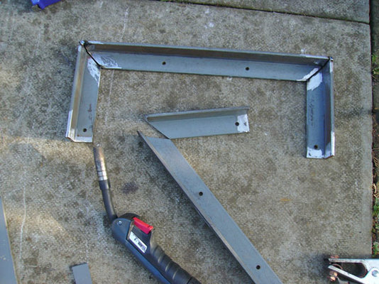
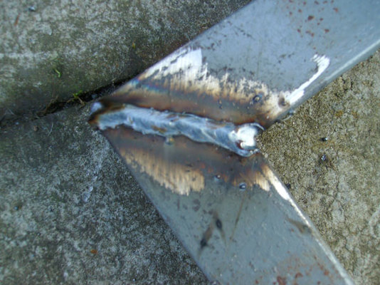
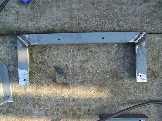
Now to clamping up.I took the front C peice, measured in 4.5" from each side and drilled 2 1/2" holes. I had 2 3" long bolts with 3/4" head/nut
I welded the 3/4" nut to the hole on the angle, screwed in the bolt ,then stood a 17mm nut upright on the bolt heads and welded those, next was a
3" long bolt through the 17mm nut ,welded the nut and there we have nice little handles ..... Hmmmm bodgey-licious
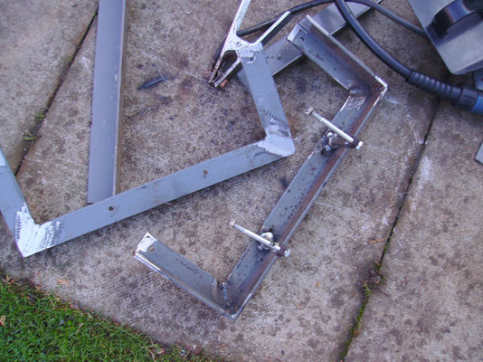
Putting it all together, I took the 2 x11" peices of 2 x1.5" angle, the wider face as the base and welded the the "C" with clampy bits 3" inside.
The second C peice needs to be higher than the first to compensate for the loose peice of angle that acts as the jaw.
Because i felt i'd already exeeded my hack sawing quota for the day and hadnt cut the front uprights 3/16 shorter i used a peice 2" square
3/16" thick as a pad on the base then welded in the second "C" peice this ensured that the horizontal peices are all flush when clamped up.
I left approx 1/2" gap between the 2 "C" peices to act as the throat ,as it were.
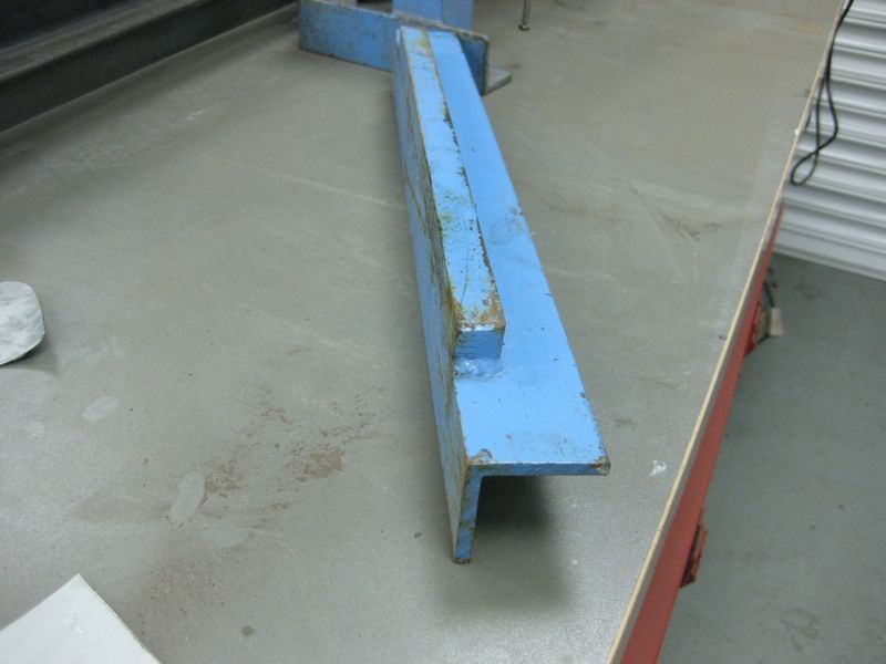
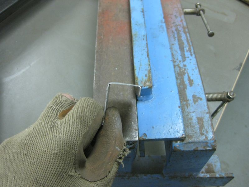
Finished - with a peice of 1mm zintec bashed into 1" angle
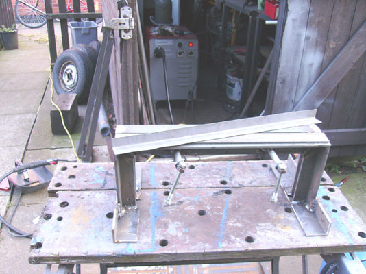
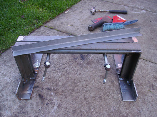
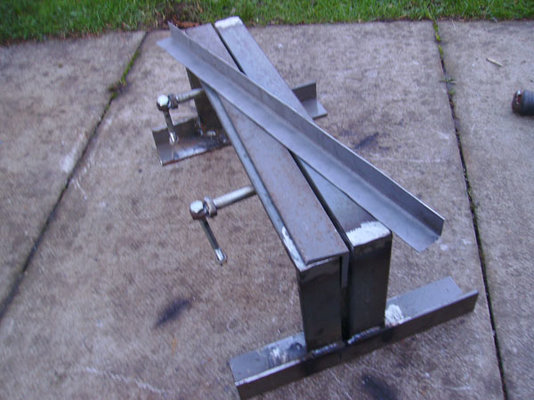
There you go ..... a bit primative , but will deffo come in handy bending bits of tin to stick on rusty cars.
I hope the images explain better than my write up
Its simple as its just a vice type grip, aimed at making floor to sill , chassis pieces etc , clamp the sheet in and bash it about a bit.
It isnt made to any particular plan , just sized to suit the materials i had at hand, which were 2 peices of 1.5" x 1.5" x 1/4" angle 32" long
and a length of 2" x 1.5" x 3/16" approx.
Now the hard part, as my only means of cutting the material to size is my cheap hacksaw that always tries to cut on the slant , and
a wobbly B&D workmate.
First i got the 2 lengths of 1.5" angle , marked them off square 7" in from each end then marked the 45deg angles, i cut the triangle
peices first and snapped them out with mole grips then cut them off square at the 7" mark, not ideal but easy to face up with the grinder.
That gave me 4 uprights at 7" and the horizontal peices at about 18"
Next i cut the 2 x 1.5" , 2 peices at 11" long to use as the base and a peice at 18" to "float" int the jaw.
Bloody arms were aching by now....

Firstly made up 2 "C" shapes from the 1.5" angle bits, i left about 1/8" gap on the joints to help me get my dodgy cutting sqare
and get a good penetration with weld .I welded back and front ,then flatted the weld on the fronts that were going to be the inside of the jaw.


Now to clamping up.I took the front C peice, measured in 4.5" from each side and drilled 2 1/2" holes. I had 2 3" long bolts with 3/4" head/nut
I welded the 3/4" nut to the hole on the angle, screwed in the bolt ,then stood a 17mm nut upright on the bolt heads and welded those, next was a
3" long bolt through the 17mm nut ,welded the nut and there we have nice little handles ..... Hmmmm bodgey-licious


Putting it all together, I took the 2 x11" peices of 2 x1.5" angle, the wider face as the base and welded the the "C" with clampy bits 3" inside.
The second C peice needs to be higher than the first to compensate for the loose peice of angle that acts as the jaw.
Because i felt i'd already exeeded my hack sawing quota for the day and hadnt cut the front uprights 3/16 shorter i used a peice 2" square
3/16" thick as a pad on the base then welded in the second "C" peice this ensured that the horizontal peices are all flush when clamped up.
I left approx 1/2" gap between the 2 "C" peices to act as the throat ,as it were.

Finished - with a peice of 1mm zintec bashed into 1" angle


There you go ..... a bit primative , but will deffo come in handy bending bits of tin to stick on rusty cars.
I hope the images explain better than my write up


