gavcarter
Member
- Messages
- 458
- Location
- Hartlepool
Ripped this off another forum I frequent, built this little lathe years ago for making air rifle parts, threading gun barrels and other little odd jobs.
Hopefully will get someone by, when they cant find afford a machinist. Or maybe like me you just see it as a challenge and get stuck in?
To start with you need a solid base with two uprights on it, and further upright on the back of the rear upright. I used 6" steel girder, with a 10mm base and 12 mm legs. Nice and solid


As you can see i have already mounted my motor to the side of the bed, and i have ground out ( quite scruffily) slots for the spindle to sit in - i was not going to try and drill two 30mm holes precisely in this stuff!!
Next is to attach the spindle - i picked 30mm ID 55mm OD bearings that are part of a transit van driveline ( the differential i think) so they should stand up to a few 1000rpm and sideways loads.
I used 1/2 thick aluminium plate to mount them in - you could use a hole saw for this but as i made the holes too small, i had to finish boring them out on a mates lathe.

the bearing should just about drop through the hole - you dont want a tight fit.
Next we drill two holes down the sides of the bearing hole making sure to go well past the halfway mark ( half the diameter of the bearing hole). then hacksaw the mounts in half leaving you with a big plate with a U on top and a small plate with a U on the bottom.
Drill out the holes in the small plate so your chosen bolts can pass through and drill the bottom plate a bit deeper then tap for your chosen bolts

As you can see there is a slot in this plate and there should also be a slot in the other plate but running in the opposite direction. Hold the bottom part of the mount onto the support ( of the lathe ) and drop the spindle on top, and eye up roughly where it needs to be and mark the centre of the slot in the support for drilling. Do this either end and drill them to take bolts - i used M8.
Now bolt on both the mounts via the slots and nip them tight-ish you will be shuffling them round with a hammer in a minute
pop your spindle in and tighten down the top parts of the mounts so its nice and solid, put some thing in the chuck and centre it using a run out gauge ( if you have a three jaw you will just have to trust it is straight)
pop your slides or carriage way ( cross vice for me ) where they should go - roughly aligned with the spindle

now you start levelling the spindle out using digital vernier and a small engineers set square measure the distance between the bottom rail ( this is important that you measure the bottom rail and not part of the frame etc, the spindle wants to be level with the ground surface that the tool post slides SIDEWAYS on)
Adjust the spindle mount by tapping with a hammer until you are sure it is very close to being perfectly level.
once it is level look at it from above and make sure it runs parallel to the cross slides. I attached G-clamps to my mounts to stop them moving then drilled another four 8mm holes through the mounts and the steel, and fastened it in with M8 bolts, your spindle should now be rock solid in place.
Now you have to align the cross slides with the spindle, i did this by tapping 6 x M6 bolts into the bed and then nipping the cross slide up.
take a very small and slow cut of your test peice about two inches long and measure each end, you then tap the crosslide with a hammer until it is sat straight with the test peice and do another cut to check.
I have got mine to 0.03 over two inches but its not finished yet so i will true that up later - if i can!
Now double check your height measurements just in-case its moved whilst drilling, bolting etc, if it has moved and your spindle is already bolted securely you can use shims under the slides to level it back off.
Once you are happy its all done tighten the crosslide down as good as you can - if its not cast iron like mine weld the bugger down!
Finally pour over a tin of hammerite, do not attempt to brush it on neatly this is not how hammerite works - just dip your brush in an slap it on

My motor and pulleys came from a wood lathe and provided speeds of 850,1200, 1600 and 2000RPM.
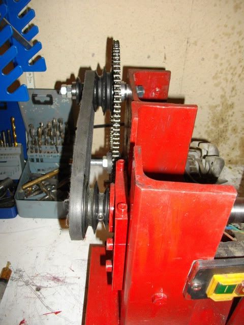
All of which are too fast for machining steel or larger diameter aluminium. I could have just changed the pulley sets but they are opposite and equal for the different speeds. This means id either have to get two sets the same, or build a tensioner for the belt. I instead opted for a primary chain drive
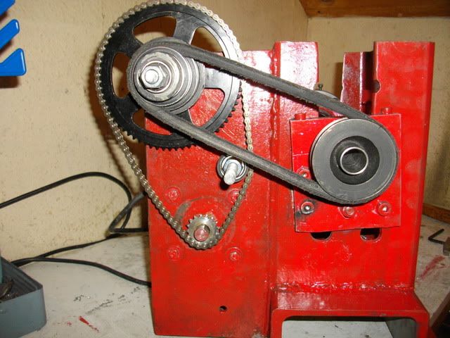
Firstly i decided by how much i want to reduce the speed which is a quarter. So i need two sprockets one three times bigger than the other i picked up a 17tooth and a 68tooth sprocket on ebay for well under a tenner ( mini moto parts :wink: :lol: ) and a 6mm pitch chain for about £4.
The chain runs from the motor to a primary shaft and the belt runs form the primary shaft to the lathe slowing the lathe by roughly a quarter but still letting me choose three gears. ( id still have all four if i had used a smaller diameter lathe spindle)
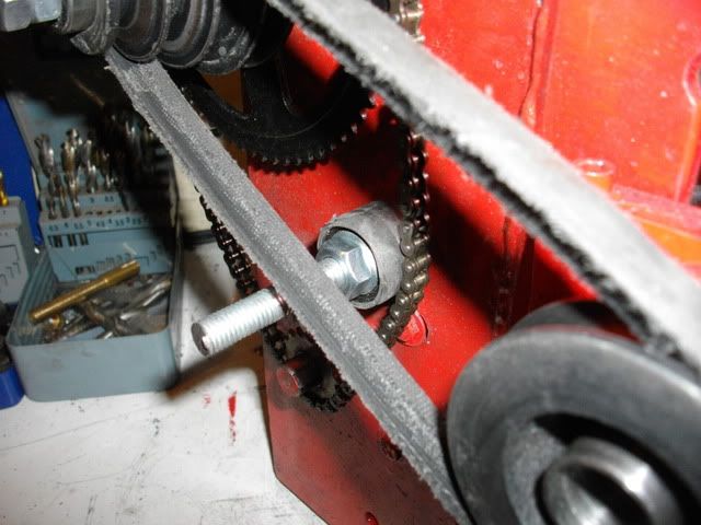
The primary shaft is a short length of M10 studding, the big mini moto sprocket sits on a machined peice of aluminium that has a bearing encased in to ( just visible between the lathe and the sprocket) and also include a 14mm shaft for the pulley to fasten on with.
The smaller end of the pulley also has bearings on it ( but as its part of the lathe drive i couldnt machine it so i had to run the motor with no belt, and use a file to put in a taper on the end of the pulley set for the bearing to locate in and hold the pulley central.)
Quick video showing the changes the speeds between the different spindles, i know it can be hard to understand at first so i have stuck some tape to all the pulleys and sprockets so you can see how they rotate in relation to each other.
God knows what sh** is on the radio it was almsot four years ago :wink:
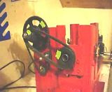
Hopefully will get someone by, when they cant find afford a machinist. Or maybe like me you just see it as a challenge and get stuck in?
To start with you need a solid base with two uprights on it, and further upright on the back of the rear upright. I used 6" steel girder, with a 10mm base and 12 mm legs. Nice and solid
As you can see i have already mounted my motor to the side of the bed, and i have ground out ( quite scruffily) slots for the spindle to sit in - i was not going to try and drill two 30mm holes precisely in this stuff!!
Next is to attach the spindle - i picked 30mm ID 55mm OD bearings that are part of a transit van driveline ( the differential i think) so they should stand up to a few 1000rpm and sideways loads.
I used 1/2 thick aluminium plate to mount them in - you could use a hole saw for this but as i made the holes too small, i had to finish boring them out on a mates lathe.
the bearing should just about drop through the hole - you dont want a tight fit.
Next we drill two holes down the sides of the bearing hole making sure to go well past the halfway mark ( half the diameter of the bearing hole). then hacksaw the mounts in half leaving you with a big plate with a U on top and a small plate with a U on the bottom.
Drill out the holes in the small plate so your chosen bolts can pass through and drill the bottom plate a bit deeper then tap for your chosen bolts
As you can see there is a slot in this plate and there should also be a slot in the other plate but running in the opposite direction. Hold the bottom part of the mount onto the support ( of the lathe ) and drop the spindle on top, and eye up roughly where it needs to be and mark the centre of the slot in the support for drilling. Do this either end and drill them to take bolts - i used M8.
Now bolt on both the mounts via the slots and nip them tight-ish you will be shuffling them round with a hammer in a minute
pop your spindle in and tighten down the top parts of the mounts so its nice and solid, put some thing in the chuck and centre it using a run out gauge ( if you have a three jaw you will just have to trust it is straight)
pop your slides or carriage way ( cross vice for me ) where they should go - roughly aligned with the spindle
now you start levelling the spindle out using digital vernier and a small engineers set square measure the distance between the bottom rail ( this is important that you measure the bottom rail and not part of the frame etc, the spindle wants to be level with the ground surface that the tool post slides SIDEWAYS on)
Adjust the spindle mount by tapping with a hammer until you are sure it is very close to being perfectly level.
once it is level look at it from above and make sure it runs parallel to the cross slides. I attached G-clamps to my mounts to stop them moving then drilled another four 8mm holes through the mounts and the steel, and fastened it in with M8 bolts, your spindle should now be rock solid in place.
Now you have to align the cross slides with the spindle, i did this by tapping 6 x M6 bolts into the bed and then nipping the cross slide up.
take a very small and slow cut of your test peice about two inches long and measure each end, you then tap the crosslide with a hammer until it is sat straight with the test peice and do another cut to check.
I have got mine to 0.03 over two inches but its not finished yet so i will true that up later - if i can!
Now double check your height measurements just in-case its moved whilst drilling, bolting etc, if it has moved and your spindle is already bolted securely you can use shims under the slides to level it back off.
Once you are happy its all done tighten the crosslide down as good as you can - if its not cast iron like mine weld the bugger down!
Finally pour over a tin of hammerite, do not attempt to brush it on neatly this is not how hammerite works - just dip your brush in an slap it on
My motor and pulleys came from a wood lathe and provided speeds of 850,1200, 1600 and 2000RPM.
All of which are too fast for machining steel or larger diameter aluminium. I could have just changed the pulley sets but they are opposite and equal for the different speeds. This means id either have to get two sets the same, or build a tensioner for the belt. I instead opted for a primary chain drive
Firstly i decided by how much i want to reduce the speed which is a quarter. So i need two sprockets one three times bigger than the other i picked up a 17tooth and a 68tooth sprocket on ebay for well under a tenner ( mini moto parts :wink: :lol: ) and a 6mm pitch chain for about £4.
The chain runs from the motor to a primary shaft and the belt runs form the primary shaft to the lathe slowing the lathe by roughly a quarter but still letting me choose three gears. ( id still have all four if i had used a smaller diameter lathe spindle)
The primary shaft is a short length of M10 studding, the big mini moto sprocket sits on a machined peice of aluminium that has a bearing encased in to ( just visible between the lathe and the sprocket) and also include a 14mm shaft for the pulley to fasten on with.
The smaller end of the pulley also has bearings on it ( but as its part of the lathe drive i couldnt machine it so i had to run the motor with no belt, and use a file to put in a taper on the end of the pulley set for the bearing to locate in and hold the pulley central.)


Quick video showing the changes the speeds between the different spindles, i know it can be hard to understand at first so i have stuck some tape to all the pulleys and sprockets so you can see how they rotate in relation to each other.
God knows what sh** is on the radio it was almsot four years ago :wink:


