You are using an out of date browser. It may not display this or other websites correctly.
You should upgrade or use an alternative browser.
You should upgrade or use an alternative browser.
Lobster back pipe
- Thread starter sarge
- Start date
chunkolini
celebrity artiste
- Messages
- 9,670
- Location
- Swansea
Sorry to sound ignorant, what is lobster backing?
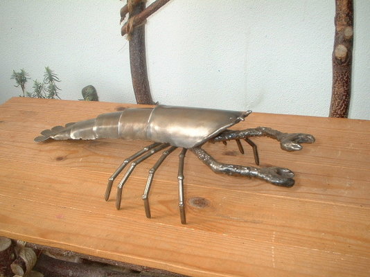
I was half expecting to see a surrealist lobster exhaust pipe, something I have genuinely considered making.
Chunko'.
I was half expecting to see a surrealist lobster exhaust pipe, something I have genuinely considered making.
Chunko'.
Say you want a 90 degree change of direction in tube.
You cut it at 45 degrees, rotate one half through half a turn, and youve got a 90 mitre corner.
But say you wanted more of a bend than a mitre?
OK, cut the the tube at 22.5 degrees (half of 45...) turn the piece still in the saw through half a turn, slide it forward a little and cut another piece off.
This time you end up with a "pie wedge" and by rotating all three pieces you can make a 90 degree joint that starts to look more like a bend.
If you made 7.5 degree cuts, then each sucessive cut gives you 15 degrees of bend when it's rewelded, so 6 of them would give the 90 degrees and that's starting to look quite a lot like a bend from a distance, but not unlike the back of a lobster from close up.
The radius of the "bend" is controlled by how much the material (because you can do this with square or rectangular section too) is moved along for each cut, the further it's moved, the larger the radius of the "bend" in effect.
Spirals and helixes are doable as well by varying the amount the material is moved between each cut and/or not quite rotating the tube through 180 degrees for each cut.
For less ambitious people who just want to make a simple bend, attaching a piece of angle iron or similar to the end of round section material to form a "T" lets you measure the half turn by sitting a spirit level on the flat face.
Hi
On a 180 degree bend is there a calculation for say:-
12 welds of 15 deg, giving 180 deg turn, how would i calculate the distance they would be apart at the ends.
Regards
Thanks for the help
On a 180 degree bend is there a calculation for say:-
12 welds of 15 deg, giving 180 deg turn, how would i calculate the distance they would be apart at the ends.
Regards
Thanks for the help
Say you want a 90 degree change of direction in tube.
You cut it at 45 degrees, rotate one half through half a turn, and youve got a 90 mitre corner.
But say you wanted more of a bend than a mitre?
OK, cut the the tube at 22.5 degrees (half of 45...) turn the piece still in the saw through half a turn, slide it forward a little and cut another piece off.
This time you end up with a "pie wedge" and by rotating all three pieces you can make a 90 degree joint that starts to look more like a bend.
If you made 7.5 degree cuts, then each sucessive cut gives you 15 degrees of bend when it's rewelded, so 6 of them would give the 90 degrees and that's starting to look quite a lot like a bend from a distance, but not unlike the back of a lobster from close up.
The radius of the "bend" is controlled by how much the material (because you can do this with square or rectangular section too) is moved along for each cut, the further it's moved, the larger the radius of the "bend" in effect.
Spirals and helixes are doable as well by varying the amount the material is moved between each cut and/or not quite rotating the tube through 180 degrees for each cut.
For less ambitious people who just want to make a simple bend, attaching a piece of angle iron or similar to the end of round section material to form a "T" lets you measure the half turn by sitting a spirit level on the flat face.
Info here on lobster back bends, I haven't tried the download.
http://www.tyharness.co.uk/lobsterback/lobsterback.htm
Zeus charts also have formula, or they used to??
http://www.tyharness.co.uk/lobsterback/lobsterback.htm
Zeus charts also have formula, or they used to??
- Messages
- 13,483
- Location
- England
Hi
On a 180 degree bend is there a calculation for say:-
12 welds of 15 deg, giving 180 deg turn, how would i calculate the distance they would be apart at the ends.
Regards
Thanks for the help
It all depends on how long you cut each section. I always find the easiest way is to draw it out, full size or scaled. Mark off equals for the lobster back, from the centre point, then that will tell you how long to cut each section.
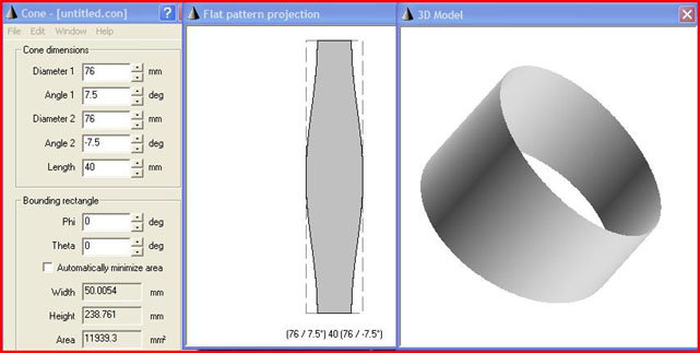
For a free cone development program that will also do segmental bends, look here, you can export them into autocad and print out patterns, not as much fun as drawing a pattern by hand though.
Nothing there concerning segmental bends.
Paul.
Moderator
- Messages
- 7,017
- Location
- Northampton. UK
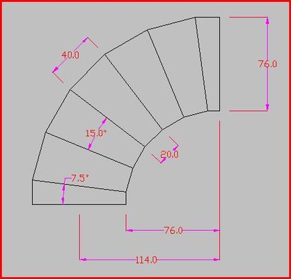
You certainly can use it to make a template for segmental bends rolled from sheet, or to make a pattern to wrap around a tube to get a cutting line, First you need to lay the bend out, as Hitch said, to obtain some measurements, this is a 6 segment 90 deg bend from 76 dia tube with a 76 inside rad.

Then use the obtained dimensions in the cone program to develop a pattern, then either import it into autocad, or print it direct from the program


Then use the obtained dimensions in the cone program to develop a pattern, then either import it into autocad, or print it direct from the program

weldingscotty803
what you staring at??????????
- Messages
- 1,172
we mitre alot of our pipe at work, then butt weld it using abf machithnes. but thats with plastic pipe. mostly yellow pipe for gas amd loads for landfill. if you have a look in my album you will see a speed boat which was made using this method. but using bigger pipe only 400mm dia. lol
we have to do alot of mitres for bryan donkins. we normally do a template on the floor first then we can add the amount of pipe used etc during the welding process we need to leave between 6and 12 mm for smaller dia pipe and upto 40mm for 630mm sdr 11. wall is very thick on that pipe. off the top of me head i think its near on 120mm thick. not used very much
anyway i will stop boring you now
atb scott
chunkolini
celebrity artiste
- Messages
- 9,670
- Location
- Swansea
weldingscotty803
what you staring at??????????
- Messages
- 1,172
nice one chunko. one of your creations?
Bullyterrier
So Mote It Be
- Messages
- 267
weldingscotty803
what you staring at??????????
- Messages
- 1,172
nice one runnach lol


