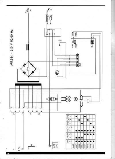
My trusty welder packed in this morning and I'm struggling to find any decent information about it. It's a Cebora Boxer 185 (ART 534)
I've done some basic tests on it and I'm pretty certain it's a problem on the PCB but I've completely failed to find any information, wiring diagrams for the welder or a schematic for the PCB. The welder is not even listed on the Cebora site in their parts lists.
Can anyone give me some pointers ? I'm more than capable of fixing the PCB if I can figure out what's wrong with it. Looking at the PCB and tracing it manually it seems as if there's a problem with the low voltage circuit that would normally supply 24v DC to trigger the on board relay through the torch switch - there's no power at all to the switch and then the relay. If I short the relay contacts on the PCB the main transformer and gas solenoid are activated via the circuit breaker but no wire feed as I assume that's fed from the low voltage circuit too.
It looks like the low voltage circuit is a simple transformer/bridge rectifier/smoothing setup all on board the PCB so I'm assuming the problem is in there, particularly as what I'm guessing is the primary winding on the transformer looks to be open circuit - with no circuit diagram it may be that I'm testing the wrong pins although what I'd guess is the secondary winding is showing about 40 ohms which is reasonable.


