greyshirtguy
Persistent Learner
- Messages
- 150
Disclaimer: "Ok, as well as enjoying all things DIY (esp metal work) I'm a also computer nerd and try-hard hardware hacker (eg I love the kind of things you find on www.hackaday.com)"
Having learned how important a stable wire-feed is for successful MIG welding (This is a great site, Malcolm) - I felt curious to measure "how good is my little hobby MIG welders' wire-feed?"
After a little brainstorming I came up with a quick method so my laptop could measure and record it (to an accuracy of approx 4mm):
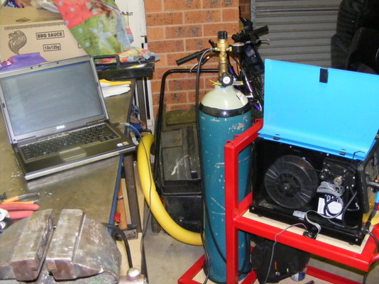
It's a bit hard to see in the first pic, so take a closer look:
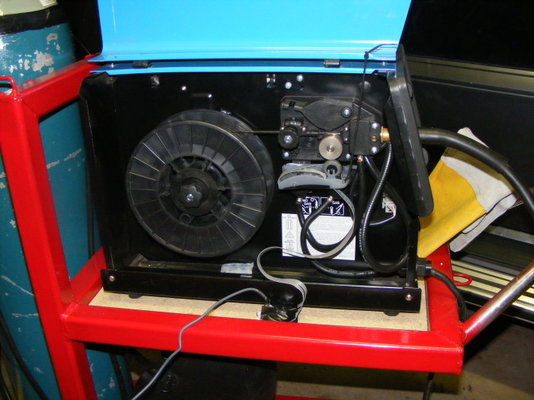
Notice the grey thing in there, with the grey cable coming out of it?
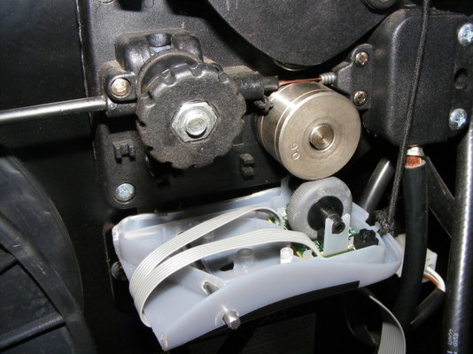
Yep, it's an old USB computer mouse!
After some tinkering and improvising, I found a way to mount a (slightly dis-assembled) mouse so that the wire feed roller movement would be captured by the scroll wheel on the mouse.
I then wrote a (quick and dirty) .NET application to record the mouse wheel movements (18 "pulses" are captured per revolution of the mouse wheel)
I then ran a steel rule carefully over the wheel to record how many pulses in 600mm - which gave a (probably not too) rough calibration.
Now that it was mounted, talking to the PC and calibrated I was ready to record my wire feeder and make some pretty charts in Excel.
Any deviations in wire feed speed would show up most clearly in a chart (instead of a nice straight line - it would have curves/bumps in it).
So I did 10 quick test welds on some 1.2mm mild steel with various power and wire-feed settings and charted the wire-feed over the whole experience. I was glad to see what were acceptably straight lines (indicating a stable feed rate during each weld)
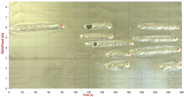
The vertical axis is metres of wire (wow! It didn't take very long to use up 8 metres of MIG wire ). The horizontal axis is time (in seconds). Each of the 10 test welds shows up as an upward sloping line with a (flat-line) pause in between. Weld 9 shows the adjustment in wirespeed made during it.
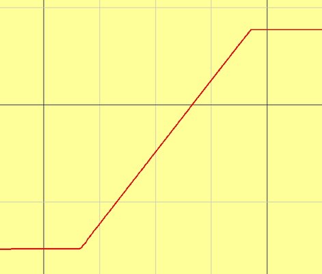
A close up of one weld shows the stability of the wire feed more clearly:
In some other tests not shown in this chart, I did notice that some really low speeds were not as stable on the higher voltage settings (thankfully they were way too slow to be used at those settings)
I understand most people might not see the "sense" in this project - but it was (for me) a really fun night, and I think I will do some more accurate calibrating and some more recording when welding again.
Having learned how important a stable wire-feed is for successful MIG welding (This is a great site, Malcolm) - I felt curious to measure "how good is my little hobby MIG welders' wire-feed?"
After a little brainstorming I came up with a quick method so my laptop could measure and record it (to an accuracy of approx 4mm):

It's a bit hard to see in the first pic, so take a closer look:

Notice the grey thing in there, with the grey cable coming out of it?

Yep, it's an old USB computer mouse!
After some tinkering and improvising, I found a way to mount a (slightly dis-assembled) mouse so that the wire feed roller movement would be captured by the scroll wheel on the mouse.
I then wrote a (quick and dirty) .NET application to record the mouse wheel movements (18 "pulses" are captured per revolution of the mouse wheel)
I then ran a steel rule carefully over the wheel to record how many pulses in 600mm - which gave a (probably not too) rough calibration.
Now that it was mounted, talking to the PC and calibrated I was ready to record my wire feeder and make some pretty charts in Excel.
Any deviations in wire feed speed would show up most clearly in a chart (instead of a nice straight line - it would have curves/bumps in it).
So I did 10 quick test welds on some 1.2mm mild steel with various power and wire-feed settings and charted the wire-feed over the whole experience. I was glad to see what were acceptably straight lines (indicating a stable feed rate during each weld)

The vertical axis is metres of wire (wow! It didn't take very long to use up 8 metres of MIG wire
 ). The horizontal axis is time (in seconds). Each of the 10 test welds shows up as an upward sloping line with a (flat-line) pause in between. Weld 9 shows the adjustment in wirespeed made during it.
A close up of one weld shows the stability of the wire feed more clearly:

In some other tests not shown in this chart, I did notice that some really low speeds were not as stable on the higher voltage settings (thankfully they were way too slow to be used at those settings)
I understand most people might not see the "sense" in this project - but it was (for me) a really fun night, and I think I will do some more accurate calibrating and some more recording when welding again.
Last edited:


