


- Forums
- Tools, Compressors and Metal Coatings
- Tools, Materials and Techniques
- Machining
- Machining Techniques and Materials
You are using an out of date browser. It may not display this or other websites correctly.
You should upgrade or use an alternative browser.
You should upgrade or use an alternative browser.
Anyone gear cut a pinion?
- Thread starter minimutly
- Start date
No, I just eyeballed it. The point being, I'm not trying to measure the deflection, just note it, and hopefully there won't be any.Pretty cool. how did you arrive at the correct curve on the pivot lever where it acts on the dial indicator point? Was it by using gauge blocks and filing to suit?
After making it I did consider remaking the pivoting part, with identical distances both sides of the pivot, but that would leave the curve to create. Do-able, but one for later. And the tilt of the head would affect the readings as well (I think). Actually with some reverse maths it should be possible to use it to measure the spiral and calculate the lead, but seeing as even my last, best attempts at calculating this was some way off I expect it would be a frustrating exercise to say the least...
I'm still an amateur messing about in the dark, but my last attempt at an aluminium pinion is 95% there, so I'm making some progress I think.
Pete.
Member
- Messages
- 14,176
- Location
- Kent, UK
You're right that the tip will tend to incur cosine errors but the fact that you're measuring an arc distance using a linear device will incur more.
Probably more accurate (and a lot less work) would be to turn a small pulley which had an OD equal to your gear's pitch diameter and fix it to the pinion shaft. Put your shaft between centre's or on a vee block, set a stop to act on the pitch diameter of one tooth pair. Now traverse the shaft axially so it turns as you move it, and use a string or wire wrapped around the little pulley to measure the distance rotated. Use trig to get your helix angle.
Probably more accurate (and a lot less work) would be to turn a small pulley which had an OD equal to your gear's pitch diameter and fix it to the pinion shaft. Put your shaft between centre's or on a vee block, set a stop to act on the pitch diameter of one tooth pair. Now traverse the shaft axially so it turns as you move it, and use a string or wire wrapped around the little pulley to measure the distance rotated. Use trig to get your helix angle.
Pete.
Member
- Messages
- 14,176
- Location
- Kent, UK
Umm, after looking at the pic again it looks like you're driving the original gear past the pointer using the table travel and DH gear train, then adjusting the lead via the gear train until the pointer shows no movement. If that's what you're doing it's very clever and should produce a perfect copy.
That's exacty what I've done. Ended up with zero error in the actual gear, but a different lead to that given by the textbooks.... It would have been nice to have the two exactly the same. Do I try to work ot where the error is (by evaluating every calculation to the nth degree), or just put it down to my pinion being a small tooth count non standard barsteward?Umm, after looking at the pic again it looks like you're driving the original gear past the pointer using the table travel and DH gear train, then adjusting the lead via the gear train until the pointer shows no movement. If that's what you're doing it's very clever and should produce a perfect copy.
Pics of latest effort, now I have to ascertain the exact helix angle to ensure the cutter cuts how it’s meant to..
Last edited:
Well, it’s engaging fine, but measuring the actual angle has been one of the difficulties. And this angle is the primary input of the calculation of the lead. The other being the pitch diameter of the gear. So now I know the lead, I have a pinion that closely matches the original, and sits squarely on the (slightly imperfect) rack.
The setting of the table on the mill has no effect on the lead, but it does affect the tooth profile. If I reverse calculate the equation that gave me the (wrong) lead, do I use the original, calculated pitch diameter, and derive the angle, or do I assume the angle as measured is correct and derive a new pitch diameter?
I’m tempted to use my tool to asses the tooth angle on the rack before going further, this will hopefully give me the table set angle and I can use this to recheck the lead calculation.
Did you follow that? I’m not sure I did...
Don't know if it would ever be of any help but I have a 3d printer and a resin printer. If you ever needed a gear creating as a sample for you to take measurements off etc let me know.Well, it’s engaging fine, but measuring the actual angle has been one of the difficulties. And this angle is the primary input of the calculation of the lead. The other being the pitch diameter of the gear. So now I know the lead, I have a pinion that closely matches the original, and sits squarely on the (slightly imperfect) rack.
The setting of the table on the mill has no effect on the lead, but it does affect the tooth profile. If I reverse calculate the equation that gave me the (wrong) lead, do I use the original, calculated pitch diameter, and derive the angle, or do I assume the angle as measured is correct and derive a new pitch diameter?
I’m tempted to use my tool to asses the tooth angle on the rack before going further, this will hopefully give me the table set angle and I can use this to recheck the lead calculation.
Did you follow that? I’m not sure I did...
Pete.
Member
- Messages
- 14,176
- Location
- Kent, UK
The helix angle of the rack will be constant across the tooth form, because the rack is straight. It should match the angle of the pinion at the pitch line but not necessarily at the root or tip, because a helical gear just like a worm has a different helix angle at the base circle than at the OD. For a larger helical gear the difference will probably be negligible so you should be able to roll a large helical gear on paper and measure the angle directly with a good protractor from the impression made but for a low tooth count pinion the difference will be significant as the tooth height forms a significant part of the gear's diameter. You'll need to measure the lead angle at the actual pitch line.
That's the beauty of your method, you don't actually need to know the lead angle you just need to copy it. So long as the original pinion is not worn out of shape you'll get a perfect fit.
As far as your pitch diameter is concerned, I would forget about calculations. I'd simply set up the blank of the same OD, rig up the helical drive as you have it and keep cutting until the tip widths match. If it ends up being a loose fit that would be down to the old pinion being worn so I'd just cut another with less depth until I was happy with the resultant engagement.
That is the one beauty of cutting gears on a hobber. If you cut the gear and it's too tight on the engagement it's a moment's work to re-mount it on the arbor and make another pass to ease the fit. Not so easy when you're cutting with a dividing head but also not terribly difficult.
I’m lucky in that the pinion isn’t worn. The rack, being MS is certainly worn. And I have to say I’m miffed that my calculations for lead didn’t come out exactly the same as the original which I took the measurements off. I’ll get the figures when I’m down there later.
It still leaves me needing to get the correct helix angle to set the table for cutting the gear accurately, as well as the rack, which luckily I have a cutter for. (Cutting the rack will be another story, but the issues here will be accurately setting and holding the work, and accurate advancing for each tooth).
There is a fellows gear cutter just up the road from me, sitting gathering dust and rust, rather large for me though...
And yes to recutting with a dividing head, just a matter of tool and work setting, taking up backlash etc, so long as the cut isn’t too small...
The calculated lead was 5.210, indicated 4.5 thou error. 5 iterations through slightly longer and longer leads got me to 5.357 inches lead, zero indicated error. Even though I don’t have a full set of change gears most steps were attainable. My earlier attempts at calculating lead and cutting the gear used the full diameter of the gear, so we’re miles out. Potential error points are the calculated pitch diameter and the helix angle, one calculated, one measured. I’m going to measure the rack angle with my tool, which should pin down the helix angle. Then make a piece of rack gear. The easy way out would be to make the rack to match the pinion, but I’m trying to replicate the originals.I’m lucky in that the pinion isn’t worn. The rack, being MS is certainly worn. And I have to say I’m miffed that my calculations for lead didn’t come out exactly the same as the original which I took the measurements off. I’ll get the figures when I’m down there later.
It still leaves me needing to get the correct helix angle to set the table for cutting the gear accurately, as well as the rack, which luckily I have a cutter for. (Cutting the rack will be another story, but the issues here will be accurately setting and holding the work, and accurate advancing for each tooth).
There is a fellows gear cutter just up the road from me, sitting gathering dust and rust, rather large for me though...
And yes to recutting with a dividing head, just a matter of tool and work setting, taking up backlash etc, so long as the cut isn’t too small...
Made a smaller tip for my patented tool tonight, so it can get lower down between the gear teeth on the rack, so I can measure the cut angle. Turned out to be smack on 23degrees. Next to cut a rack.The calculated lead was 5.210, indicated 4.5 thou error. 5 iterations through slightly longer and longer leads got me to 5.357 inches lead, zero indicated error. Even though I don’t have a full set of change gears most steps were attainable. My earlier attempts at calculating lead and cutting the gear used the full diameter of the gear, so we’re miles out. Potential error points are the calculated pitch diameter and the helix angle, one calculated, one measured. I’m going to measure the rack angle with my tool, which should pin down the helix angle. Then make a piece of rack gear. The easy way out would be to make the rack to match the pinion, but I’m trying to replicate the originals.
The first rack. This is not a test, I've fitted it with an existing pinion and it's smooth and accurate, if I'm honest the marking up indicates it's slightly out on the cut angle, but it's small.
I machined the length of steel that tried to escape from my lathe whilst parting a job off the end, to make the fixture it's sitting in - this is the current job - to finish the fixture so I can more accurately set and cut the future racks.

Whilst cutting this I found an issue with the milling machine. The fixture needs a step in the bottom to locate on the flat on the back of the rack, but to do this I had to release the lock on the knee..(So it could be raised and lowered).
Unsurprisingly, I suppose, this caused the knee to tilt, ruining the back cut. So I had to cut the back again, in one, without the step (Which is OK since the rack is round, and the step in the back is outside the diameter of the rack.

I machined the length of steel that tried to escape from my lathe whilst parting a job off the end, to make the fixture it's sitting in - this is the current job - to finish the fixture so I can more accurately set and cut the future racks.
Whilst cutting this I found an issue with the milling machine. The fixture needs a step in the bottom to locate on the flat on the back of the rack, but to do this I had to release the lock on the knee..(So it could be raised and lowered).
Unsurprisingly, I suppose, this caused the knee to tilt, ruining the back cut. So I had to cut the back again, in one, without the step (Which is OK since the rack is round, and the step in the back is outside the diameter of the rack.
Plan is to manufacture complete rack assemblies, specifically for vintage Cooper racing cars. The first customer (freeby) is the owner of the one (worn) rack we have to replicate. These rack assemblies are unobtaneum, and the castings were originally magnesium. but we can cast them in aluminium.Great work. Is this a replacement for a worn rack or are you going to be selling these? I know of a firm in Australia making custom ratio racks for classic cars. Using the original rack body, with homemade internals. Some with power steering too, pretty cool!
It's a long term project, I've had to buy a universal milling machine and all its add-onns, and learn how to use it, buy a tool and cutter grinder, modify it to cut the form cutters to make the pinions (low tooth count helical pinion, cutter is a special).
Still lots to do - make a fixture to machine the rack casings, make a pinion from steel (so far only cut ones from ally), then go through the hardening process and see if it's hard enough, but not too hard...
Yesterday I changed the orientation of the milling machine, from horizontal to truly universal, by adding the universal cutter head for the first time. But first I had to clean and lube it, then move the mill and open the window so I had room for the overarm, and having done that, I'm having doubts the work will pass under the universal head...
These will be identical to the original (racing car racks). I'm planning not to be using anything more than drill rod (silver steel) for the pinions which I will oil quench then temper back after polishing. The issue being any distortion from this process (as well as getting the hardness right, but using a non exotic steel will surely help).For racing I expect there is a market for quicker racks too
Looks great so far. Be interested on the hardening process.
Agroshield
Member
- Messages
- 4,797
...I'm having doubts the work will pass under the universal head...
For cutting a rack, you do not necessarily need a multi-tooth cutter of the style you show. A flycutter would do it and allow you to use a larger swept diameter so the work passes under the head.
The other option is a multi-tooth cutter of larger diameter.
See:
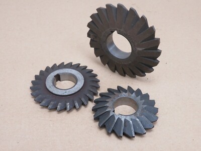
SYMMETRICAL EQUAL ANGLE MILLING CUTTERS TO FLAT FOR HORIZONTAL MILLING MACHINE | eBay
We will always help you to have a 100% positive happy buying experience.
www.ebay.co.uk
The listing has 40 degree included angle and 30 degree included angle (which might need to be reground to 29 degree). Note the available diameters - more than 3".
You can also use a longer arbor but with the plain portion of rod after the teeth, that might be so long as to be too floppy.
Yeah, worked out I needed a bigger cutter, not so keen on a long overhang, or a flycutter tbh.For cutting a rack, you do not necessarily need a multi-tooth cutter of the style you show. A flycutter would do it and allow you to use a larger swept diameter so the work passes under the head.
The other option is a multi-tooth cutter of larger diameter.
See:
SYMMETRICAL EQUAL ANGLE MILLING CUTTERS TO FLAT FOR HORIZONTAL MILLING MACHINE | eBay
We will always help you to have a 100% positive happy buying experience.www.ebay.co.uk
The listing has 40 degree included angle and 30 degree included angle (which might need to be reground to 29 degree). Note the available diameters - more than 3".
You can also use a longer arbor but with the plain portion of rod after the teeth, that might be so long as to be too floppy.
Spent a couple of hours today checking the clearance with the cutter I have - nowhere close.
Then a clean of the vertical ways and adjustment of the gibs - they were all over the place, and now set as close as I could gives a nice positive locking feel, without the nut dropping away from the table