


Hello everyone, this is my first post on this nice forum ")
I have bought a second hand 3-phase 250 amps Mig welder from a guy
who renovates old welders and bring them back to live with parts from
different units.
I was wondering if any of you nice people in here could help me identify
my welder machine or parts of it, and maybe give me some tips on how to improve and upgrade it.
(NOTE: I dont have any shielding gas yet, so testing at home have been done with
flux core wire and the polarities switched.
Before purchasing the welder I was able to test it with gas though, and it worked nicely)
Some information and wonderings:
Type of welder:
The welder is labeled Telwin but clearly it is not a Telwin.
Looking at the front label it is marked as a CIFES MIG 250 (see pic)
(I have looked all over the internet but cannot find any useful information about
CIFES welders).
The duty cycle looks pretty good though, at least for me as a modest hobbyist.
I'm going from a flux core 130 Amp generic Chinese welder. So the difference is huge.
I cannot be sure that the welder really is a CIFES machine though ,
that is why I'm asking if any of you recognize the parts inside.
The transformer is aluminium-winded, but looks to be in sufficient condition. Original CIFES ?
I only have two main things (at the moment) that I would like to upgrade/install on this welder.
And those are the Choke/Inductor and perhaps the wire feeder.
The choke is a priority right now.
The Choke/Inductor:
The welder did not come with an choke, which I found a bit odd.
According to the vendor its not really necessary for a 3-phase mig welder to have
a choke. I thought it was more or less a standard for transformer based MIG welders to have chokes ?
Looking at the picture above the rectifier, there are two holes indicating that something
could have been attached there earlier. Was it a choke perhaps ?
Anyway he gave me an ESAB Power Compact 200 choke as a compensation.
I have tried the ESAB choke by connecting it to the ground clamp on the outside of the welder,
but I'm not getting a good result at all.
The arching stutters at the beginning of the weld and "sometimes" stabilizes after a short period.
The welding behavior is much smoother without the choke, so maybe the vendor was right after all ?
So what could it be ?
The choke is saturating since not being big enough for this welder ?
There is an additional tap on the choke, close to the input so I wonder if this inductor should be connected in a particular way ?
What do you guys think about moving the additional tap to the middle of the wiring giving less induction as an
option (with multiple ground outputs) ?
Or maybe its a better idea to ask the vendor for another choke to test, that is larger or more suitable for this
machine ? If he is willing to offer me one, that is..
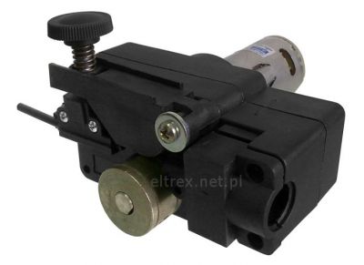
The wire feeder:
The wire feed motor looks a bit small and the assembly is plastic. Cant say that I have noticed any problems
more than that it's a bit difficult to set the tension on the wire roller.
EDIT: Actually, as I was editing the pictures and zoomed in I saw that the wire feed plastic seem to be broken around the
torch-connector. The wire feed unit was fitted an EURO-TORCH and then perhaps the plastic cover was broken
during the process. Not so nice..
According to vendor this is a Telwin wire feeder.
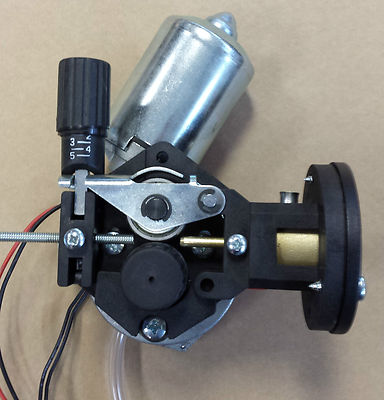
I was thinking of replacing it with a more modern common wire feeder assembly,
which has a stronger motor and aluminium casing, something like:
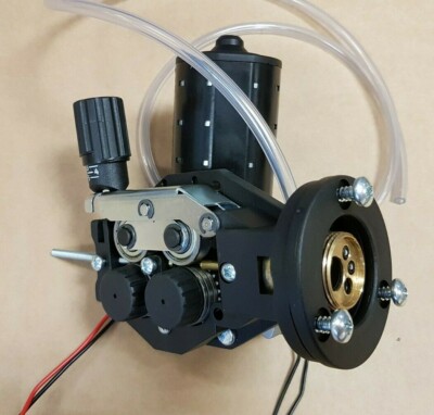
Or maybe this:
The last assembly does not look like it has a stronger motor than my machine has though..
Unfortunately the PCB appears to be rated to around 1.5- 2.5 amps. At least that is what the saftety on the front says.
So it will probably not be enough to power the more modern units ?
The (separate) transformer powering the PCB and wire feeder has higher rating than the PCB I think.
It says 100va @ 27 volt which with the help of an online calculator gives me around 3.7 amps ?
So one idea I had was to get a digital Led display PWM DC controller (for a nice visual feedback)
to replace the PCB and hook it up to the transformer with a DC rectifier in between.
something like this:
Unfortunately there are also 2 controlls for spot welding on the PCB. And those would have to go then.
I really dont think I need them. Another advantage with this new solution would be that the wiring would be simplified, and
easier to repair than if the current PCB should fail. At least theoretically...
The PCB is mounted on a removable plate attached to the welder's front. So If I create a new plate to fit the PWM controller I'm
able to restore the original PCB if I should feel like it. Would have to create connectors where cables are soldered to the PCB though..
Regarding the wiring of the PCB I'm a bit uncertain how everything goes at the moment.
Im not even sure this modification is reasonable doable..
The termal switch circuit connected to the transformer seem to go into the PCB as well.
Another simpler idea would be to get a wire-feed-unit with a smaller motor, but I'm not sure that would be much of
an upgrade then. What do you guys think ?
Comments and ideas for upgrades/tweaks are highly appreciated.
Please let me know if you want pictures from some other angles or so :-)


I have bought a second hand 3-phase 250 amps Mig welder from a guy
who renovates old welders and bring them back to live with parts from
different units.
I was wondering if any of you nice people in here could help me identify
my welder machine or parts of it, and maybe give me some tips on how to improve and upgrade it.
(NOTE: I dont have any shielding gas yet, so testing at home have been done with
flux core wire and the polarities switched.
Before purchasing the welder I was able to test it with gas though, and it worked nicely)
Some information and wonderings:
Type of welder:
The welder is labeled Telwin but clearly it is not a Telwin.
Looking at the front label it is marked as a CIFES MIG 250 (see pic)
(I have looked all over the internet but cannot find any useful information about
CIFES welders).
The duty cycle looks pretty good though, at least for me as a modest hobbyist.
I'm going from a flux core 130 Amp generic Chinese welder. So the difference is huge.
I cannot be sure that the welder really is a CIFES machine though ,
that is why I'm asking if any of you recognize the parts inside.
The transformer is aluminium-winded, but looks to be in sufficient condition. Original CIFES ?
I only have two main things (at the moment) that I would like to upgrade/install on this welder.
And those are the Choke/Inductor and perhaps the wire feeder.
The choke is a priority right now.
The Choke/Inductor:
The welder did not come with an choke, which I found a bit odd.
According to the vendor its not really necessary for a 3-phase mig welder to have
a choke. I thought it was more or less a standard for transformer based MIG welders to have chokes ?
Looking at the picture above the rectifier, there are two holes indicating that something
could have been attached there earlier. Was it a choke perhaps ?
Anyway he gave me an ESAB Power Compact 200 choke as a compensation.
I have tried the ESAB choke by connecting it to the ground clamp on the outside of the welder,
but I'm not getting a good result at all.
The arching stutters at the beginning of the weld and "sometimes" stabilizes after a short period.
The welding behavior is much smoother without the choke, so maybe the vendor was right after all ?
So what could it be ?
The choke is saturating since not being big enough for this welder ?
There is an additional tap on the choke, close to the input so I wonder if this inductor should be connected in a particular way ?
What do you guys think about moving the additional tap to the middle of the wiring giving less induction as an
option (with multiple ground outputs) ?
Or maybe its a better idea to ask the vendor for another choke to test, that is larger or more suitable for this
machine ? If he is willing to offer me one, that is..
The wire feeder:
The wire feed motor looks a bit small and the assembly is plastic. Cant say that I have noticed any problems
more than that it's a bit difficult to set the tension on the wire roller.
EDIT: Actually, as I was editing the pictures and zoomed in I saw that the wire feed plastic seem to be broken around the
torch-connector. The wire feed unit was fitted an EURO-TORCH and then perhaps the plastic cover was broken
during the process. Not so nice..
According to vendor this is a Telwin wire feeder.
I was thinking of replacing it with a more modern common wire feeder assembly,
which has a stronger motor and aluminium casing, something like:
DXX-HR Wire Feeder Motor, ZK-76ZY02AV 0.8-2.0mm Mig Welder Wire Feed Motor 24VDC 80W svetsmaskin Delar för MIG/MAG svetsare svetsmaskin : Amazon.se: Bygg, el & verktyg
DXX-HR Wire Feeder Motor, ZK-76ZY02AV 0.8-2.0mm Mig Welder Wire Feed Motor 24VDC 80W svetsmaskin Delar för MIG/MAG svetsare svetsmaskin : Amazon.se: Bygg, el & verktyg
www.amazon.se
LKAIBIN Svetsmaskin tillbehör Dc 24V Wire Feed Assembly Wire Feeder Motor Mig svetsmaskin svetsare : Amazon.se: Bygg, el & verktyg
LKAIBIN Svetsmaskin tillbehör Dc 24V Wire Feed Assembly Wire Feeder Motor Mig svetsmaskin svetsare : Amazon.se: Bygg, el & verktyg
www.amazon.se
Unfortunately the PCB appears to be rated to around 1.5- 2.5 amps. At least that is what the saftety on the front says.
So it will probably not be enough to power the more modern units ?
The (separate) transformer powering the PCB and wire feeder has higher rating than the PCB I think.
It says 100va @ 27 volt which with the help of an online calculator gives me around 3.7 amps ?
So one idea I had was to get a digital Led display PWM DC controller (for a nice visual feedback)
to replace the PCB and hook it up to the transformer with a DC rectifier in between.
something like this:
PWM Speed Controller, DC Motor Controller, Digital Display Professional för att byta industri Använd professionell användning Reparation : Amazon.se: Elektronik
PWM Speed Controller, DC Motor Controller, Digital Display Professional för att byta industri Använd professionell användning Reparation : Amazon.se: Elektronik
www.amazon.se
Unfortunately there are also 2 controlls for spot welding on the PCB. And those would have to go then.
I really dont think I need them. Another advantage with this new solution would be that the wiring would be simplified, and
easier to repair than if the current PCB should fail. At least theoretically...
The PCB is mounted on a removable plate attached to the welder's front. So If I create a new plate to fit the PWM controller I'm
able to restore the original PCB if I should feel like it. Would have to create connectors where cables are soldered to the PCB though..
Regarding the wiring of the PCB I'm a bit uncertain how everything goes at the moment.
Im not even sure this modification is reasonable doable..
The termal switch circuit connected to the transformer seem to go into the PCB as well.
Another simpler idea would be to get a wire-feed-unit with a smaller motor, but I'm not sure that would be much of
an upgrade then. What do you guys think ?
Comments and ideas for upgrades/tweaks are highly appreciated.
Please let me know if you want pictures from some other angles or so :-)


 . The flux core wire is 0.9 mm and the roller is only 0.8 mm. So that is probably causing the slipping.