


Hello everyone,
I've browsed this site quite a bit while playing with a clarke no gas mig but decided to sign up to see if anyone can help me with this problem.
I have picked up a migatronic automig with a wire feed problem. It does not appear to be the same issue as listed in this thread. http://www.mig-welding.co.uk/forum/threads/migatronic-180-automig-not-reeling-wire.36932/
Does anyone have any knowledge of these welders? I've downloaded the instruction book from migatronic website but no schematic.
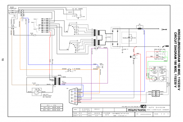
When I pull the trigger the contactor closes and a voltage appears between gun and earth clamp but I am not getting 24vDC at the motor, the thing I don't get is how it seem to be wired up. I've created a rough schematic in the attached pdf. I apologise for its poor quality but I'm very inexperience with CAD programs.
Tracing the wires and the PCB traces it appears as if one side of the motor is attached to the collector and the other to the emitter of the transistor. If I test each of the collector and emitter against another ground point on the PCB there is a 20-22 VDC when the trigger is pulled but of course there is only going to be a 1.whatever voltage drop between the collector and emitter. Its as if it is all wired up odd but the wiring is connected to the PCB via a 9 pin D plug so it should be correct as this is not something someone would change about while fiddling.
Not shown on the schematic is a small power supply transformer that supplies ~ 28 VAC to the PCB when the contactor closes. There is obviously a lot of other discrete components on the PCB but I have no chance of understanding the entire baord as I am very much a beginner in electronics.
Other info. I have replaced one of the potentiometers, removed each of the large PNP power transistors and tested them and they all seem ok. The large power smooth capacitor on the PCB looks like is might be oozing slightly but being as this is just smoothing the power this should be ok? I've tested the main power diodes on the welder and they seem ok although I'm not 100% as it is some sort of weird double plate setup that you can take apart, maybe this is some sort of old sysle power rectifying diodes?
Any pointer would be good as it just seems very odd to me.
I've browsed this site quite a bit while playing with a clarke no gas mig but decided to sign up to see if anyone can help me with this problem.
I have picked up a migatronic automig with a wire feed problem. It does not appear to be the same issue as listed in this thread. http://www.mig-welding.co.uk/forum/threads/migatronic-180-automig-not-reeling-wire.36932/
Does anyone have any knowledge of these welders? I've downloaded the instruction book from migatronic website but no schematic.
When I pull the trigger the contactor closes and a voltage appears between gun and earth clamp but I am not getting 24vDC at the motor, the thing I don't get is how it seem to be wired up. I've created a rough schematic in the attached pdf. I apologise for its poor quality but I'm very inexperience with CAD programs.
Tracing the wires and the PCB traces it appears as if one side of the motor is attached to the collector and the other to the emitter of the transistor. If I test each of the collector and emitter against another ground point on the PCB there is a 20-22 VDC when the trigger is pulled but of course there is only going to be a 1.whatever voltage drop between the collector and emitter. Its as if it is all wired up odd but the wiring is connected to the PCB via a 9 pin D plug so it should be correct as this is not something someone would change about while fiddling.
Not shown on the schematic is a small power supply transformer that supplies ~ 28 VAC to the PCB when the contactor closes. There is obviously a lot of other discrete components on the PCB but I have no chance of understanding the entire baord as I am very much a beginner in electronics.
Other info. I have replaced one of the potentiometers, removed each of the large PNP power transistors and tested them and they all seem ok. The large power smooth capacitor on the PCB looks like is might be oozing slightly but being as this is just smoothing the power this should be ok? I've tested the main power diodes on the welder and they seem ok although I'm not 100% as it is some sort of weird double plate setup that you can take apart, maybe this is some sort of old sysle power rectifying diodes?
Any pointer would be good as it just seems very odd to me.
 to exchange the board on my 180 got it fixed locally with a few other odds and sods, think it was about £65.