We'll take the axis in turn. Firstly the Z.
Now Andy used a driven nut. This has the advantage of being neat but the disadvantage of being complicated. On looking at his model I thought...Hmmm, I think you can get a suitable sized motor into the knee.

That is an 8.5Nm NEMA34/86 hybrid stepper. In theory it should work fine 1:1 as it has more torque than Andy's setup but I can always run different ratios if that's not enough (as well as for more steps per mm).
From there we needed to drive the shaft itself. Unfortunately the existing setup isn't suitable to replicate. It used thrust bearings and ran the shaft directly on the casting. Being very slow speed and into cast iron this works perfectly fine. If there had been a bronze push instead I may have considered using it anyway.

It's not fine to run at high speed and with the tension of a belt on it. Unfortunately there isn't much inside the knee to bolt a bearing to. The round section there is bridged to the front so you can't just clamp something on and the casting isn't really flat enough (anywhere) to easily bolt into. This is one where if I had other machining capability it would be easier. If I could reach down in there for example and flatten the casting so it was square I could use it to bolt to. That would need some fairly hefty machine ability though.

So I settled for making bearing holders that with a lip that would sit top and bottom into the hole for the original shaft.

This is of course where the lathe came in and appropriately as previously mentioned it's a Harrison lathe as well.
A couple of cups machined up.

These then fit into the knee on the bottom.

and top

Into these we have a set of angular contact bearings for the combination of axial and radial forces and then a "stub" shaft sits in them with some locknuts to keep it all tight.
The bottom (part way through machining so before I cut the end off cleanly).

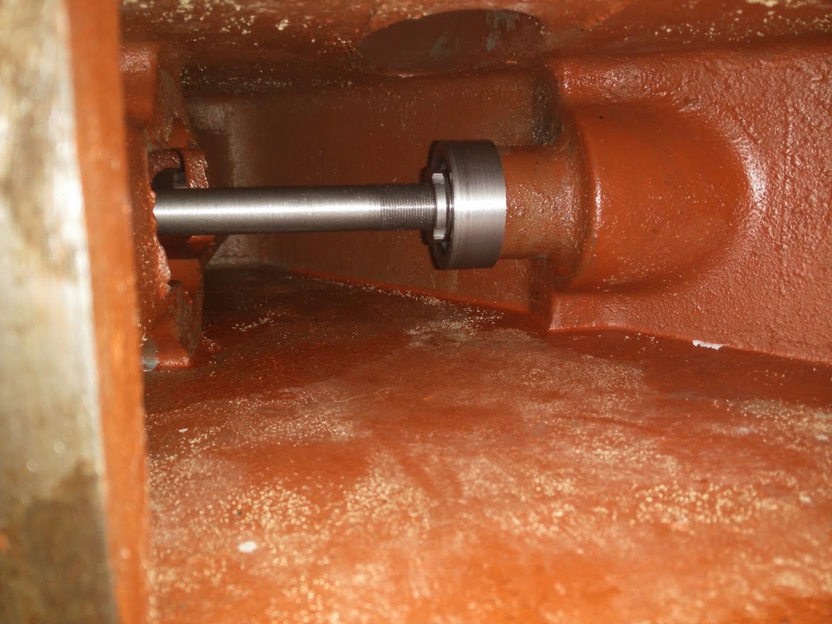
and of course top (again before I cut to length).

Next up I needed to hold the motor in place and also to tension the belt. To do this I made up a mounting plate with a holder for the bearing carrier and a eccentric tensioner. The tensioner is required because the motor literally cannot move. It has one position and can't get a belt that is the correct length.
Mounting plate from the bottom.

and with the motor in place.

What you can't see there is the bolt through the side to hold it all in place...Which was fun to transfer over to ensure I got the correct position!

To account for belt tension (because the side I had to work with fell between belt sizes) I used a pair of bearings on an eccentric mount. The tensioner is on the "slack" side of the belt, ie under normal use the weight of the knee will naturally tension the other side and there should be very little force on the tensioner itself.

This then all squeezed into the knee with a headache of assembly through the tiny slot in the top. It takes me about an hour to fit its so fiddly.

Then tested it using an arduino to generate the step/DIR to drive it from the MPG.
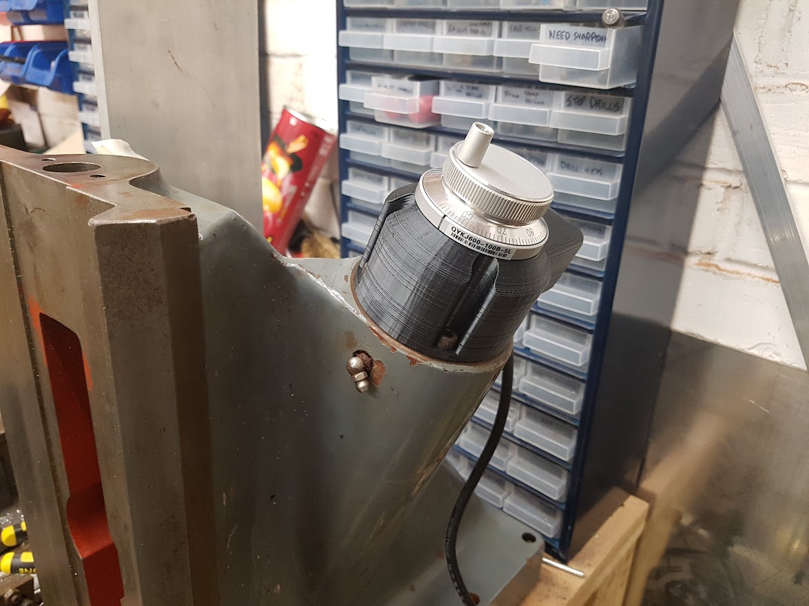
Next up we needed to run the cable out. For this I re-used the original handle hole and 3D printed a prototype for a MPG and socket mount (the socket is at the back here and points "down")

Now Andy used a driven nut. This has the advantage of being neat but the disadvantage of being complicated. On looking at his model I thought...Hmmm, I think you can get a suitable sized motor into the knee.
That is an 8.5Nm NEMA34/86 hybrid stepper. In theory it should work fine 1:1 as it has more torque than Andy's setup but I can always run different ratios if that's not enough (as well as for more steps per mm).
From there we needed to drive the shaft itself. Unfortunately the existing setup isn't suitable to replicate. It used thrust bearings and ran the shaft directly on the casting. Being very slow speed and into cast iron this works perfectly fine. If there had been a bronze push instead I may have considered using it anyway.
It's not fine to run at high speed and with the tension of a belt on it. Unfortunately there isn't much inside the knee to bolt a bearing to. The round section there is bridged to the front so you can't just clamp something on and the casting isn't really flat enough (anywhere) to easily bolt into. This is one where if I had other machining capability it would be easier. If I could reach down in there for example and flatten the casting so it was square I could use it to bolt to. That would need some fairly hefty machine ability though.
So I settled for making bearing holders that with a lip that would sit top and bottom into the hole for the original shaft.
This is of course where the lathe came in and appropriately as previously mentioned it's a Harrison lathe as well.
A couple of cups machined up.
These then fit into the knee on the bottom.
and top
Into these we have a set of angular contact bearings for the combination of axial and radial forces and then a "stub" shaft sits in them with some locknuts to keep it all tight.
The bottom (part way through machining so before I cut the end off cleanly).
and of course top (again before I cut to length).
Next up I needed to hold the motor in place and also to tension the belt. To do this I made up a mounting plate with a holder for the bearing carrier and a eccentric tensioner. The tensioner is required because the motor literally cannot move. It has one position and can't get a belt that is the correct length.
Mounting plate from the bottom.
and with the motor in place.
What you can't see there is the bolt through the side to hold it all in place...Which was fun to transfer over to ensure I got the correct position!
To account for belt tension (because the side I had to work with fell between belt sizes) I used a pair of bearings on an eccentric mount. The tensioner is on the "slack" side of the belt, ie under normal use the weight of the knee will naturally tension the other side and there should be very little force on the tensioner itself.
This then all squeezed into the knee with a headache of assembly through the tiny slot in the top. It takes me about an hour to fit its so fiddly.
Then tested it using an arduino to generate the step/DIR to drive it from the MPG.
Next up we needed to run the cable out. For this I re-used the original handle hole and 3D printed a prototype for a MPG and socket mount (the socket is at the back here and points "down")


