OK just managed to get 20 minutes in the garage.
Run the plasma up with out covers and the HF unit is not running all the time, just on start-up and when the nozzle goes over a hole when you can hear the sort of juddering when it takes out the control gear.
The power supply is a Lambda power supply as mentioned. A few pictures taken these are below and I also put back in my duff control board before I repair it. On the Y axis that still works when I move a stepper motor I get 25 Volts AC across the AP and AM connections and the same across the BP and BM windings. On a duff drive either X or Z axis I only get around 6 Volts AC. Have toi use AC on the meter during stepping as it switched pos to neg, neg to pos etc.
So not a case of one part open but both outputs of the chip just very low output.
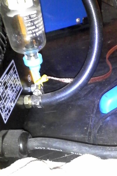
OK some pictures, first one is the grounding connection to the back of the plasma unit, ,
from here it goes to to the underside of the main frame and the disposable frame the metal being cut sits on:-
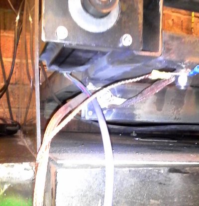
From here a grounding strap goes up to the control box, bottom left of the picture:-
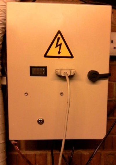
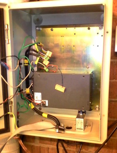
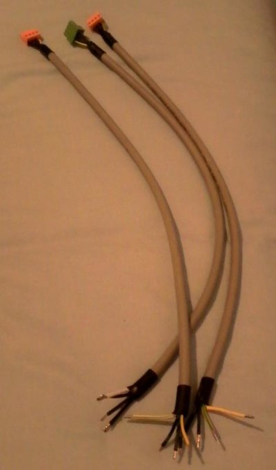
Inside shot of the box, again note the grounding stubs bottom left of the door area, three green wires go up to the screens on the output cables, also there is connection from the door earth stud to the main box earth sud and the mains is also filtered:-
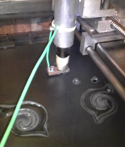
Next is the copper ground connected to the nozzle, the idea of this is to stop the sputtering, if possible and provide a sort of pilot earth. This taken from the CNC forum. The green ground wire goes off to the Clamp which is clamped again to the Plasma frame and back to the negative terminal on the plasma cutter:-
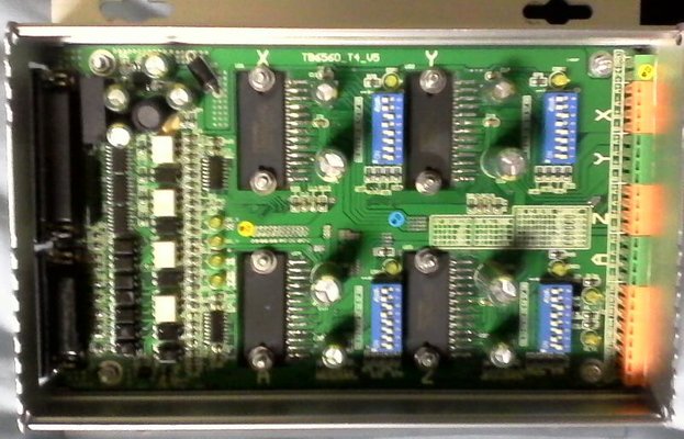
Last picture if of the board, sorry fuzzy but all taken with camera phone. left hand side is all the Opto-isolators for the input side to the TB6560 chips.
Now the negative of the PSU is connected to a common ground in the control board PCB.
I am down to 3 chips left and one controller still to fix, (I have 3), considering I did not used to have such a failure rate I am considering just having grounds between the Plasma cutter unit and the control unit. The frame I will leave just connected to the return clamp to the plasma cutter and the earth wire on the nozzle still to the clamp. basically taking the earth ground off the frame and motors.
there is no continuety between the windings and motors, but this is not to say they do not break down with the high voltage spikes from the HF.
Just thinking that rather then give the High voltage return several routes through all the grounding cables up to the control unit I will just have it going back to the Plasma.
I will post results later.
Adrian
p.s. several updates to this as I think of things. next step loose the grounding of the frame.
Run the plasma up with out covers and the HF unit is not running all the time, just on start-up and when the nozzle goes over a hole when you can hear the sort of juddering when it takes out the control gear.
The power supply is a Lambda power supply as mentioned. A few pictures taken these are below and I also put back in my duff control board before I repair it. On the Y axis that still works when I move a stepper motor I get 25 Volts AC across the AP and AM connections and the same across the BP and BM windings. On a duff drive either X or Z axis I only get around 6 Volts AC. Have toi use AC on the meter during stepping as it switched pos to neg, neg to pos etc.
So not a case of one part open but both outputs of the chip just very low output.
OK some pictures, first one is the grounding connection to the back of the plasma unit, ,

from here it goes to to the underside of the main frame and the disposable frame the metal being cut sits on:-

From here a grounding strap goes up to the control box, bottom left of the picture:-

Inside shot of the box, again note the grounding stubs bottom left of the door area, three green wires go up to the screens on the output cables, also there is connection from the door earth stud to the main box earth sud and the mains is also filtered:-

Next is the copper ground connected to the nozzle, the idea of this is to stop the sputtering, if possible and provide a sort of pilot earth. This taken from the CNC forum. The green ground wire goes off to the Clamp which is clamped again to the Plasma frame and back to the negative terminal on the plasma cutter:-

Last picture if of the board, sorry fuzzy but all taken with camera phone. left hand side is all the Opto-isolators for the input side to the TB6560 chips.

Now the negative of the PSU is connected to a common ground in the control board PCB.
I am down to 3 chips left and one controller still to fix, (I have 3), considering I did not used to have such a failure rate I am considering just having grounds between the Plasma cutter unit and the control unit. The frame I will leave just connected to the return clamp to the plasma cutter and the earth wire on the nozzle still to the clamp. basically taking the earth ground off the frame and motors.
there is no continuety between the windings and motors, but this is not to say they do not break down with the high voltage spikes from the HF.
Just thinking that rather then give the High voltage return several routes through all the grounding cables up to the control unit I will just have it going back to the Plasma.
I will post results later.
Adrian
p.s. several updates to this as I think of things. next step loose the grounding of the frame.



 But now that I have said it?