- Forums
- Tools, Compressors and Metal Coatings
- Tools, Materials and Techniques
- Machining
- Lathes and other Machining Equipment
You are using an out of date browser. It may not display this or other websites correctly.
You should upgrade or use an alternative browser.
You should upgrade or use an alternative browser.
Elliott 10M Shaper
- Thread starter RobCox
- Start date
indy4x
Forum Supporter
- Messages
- 3,323
- Location
- Pontypool, South Wales. UK
come on, lets be fair, its old and metal you like it
Whats not to like

RobCox
Member
- Messages
- 443
- Location
- Cambridge, UK
Reassembly time! I'll go through this step by step as it might help someone fixing one of these sometime in the future... or maybe not.
Starting with an empty main casting, except for the bushings which I didn't disturb as 1) they looked in good nick and 2) they've got a grub screw tapped half in the casting and half in the bush and I didn't fancy my chances of lining them up again if I'd pressed them out.
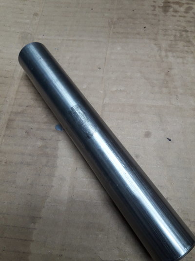
Step 1, fit the bottom spindle (the fulcrum for the rocking arm) in the body. There is wear on two sides of this so I rotated it 90 degrees to present unworn faces to the arm:
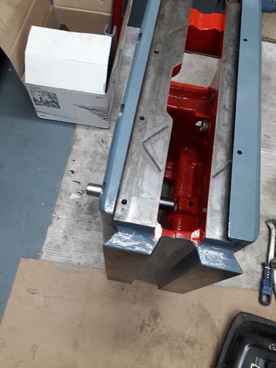
The spindle slides in the left side of the casting ok but needed a tap from a soft blow hammer to drift it into the right side. The ends of this will be visible, unlike its original state where the ends were buried in filler. Then fit the bolt which captures the end of the motor plate spring. This also locks down on the lower spindle and stops it walking out. I needed to use a universal joint on the socket to drive this:
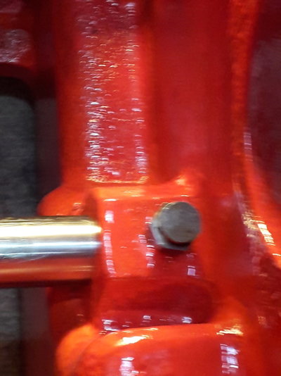
Honestly, it's not as orange as the camera and lamp make it look.
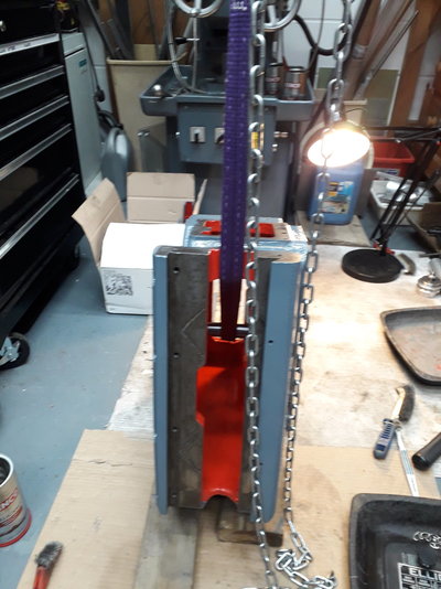
Step 2, lay the main body with the ways down. Makes it easier to fit the motor which will be placed on a horizontal surface. At this point I could just about manhandle the casting though I used the hoist. Once the motor is on it's too heavy for me to lift.
Then fit the pivot bracket for the motor...
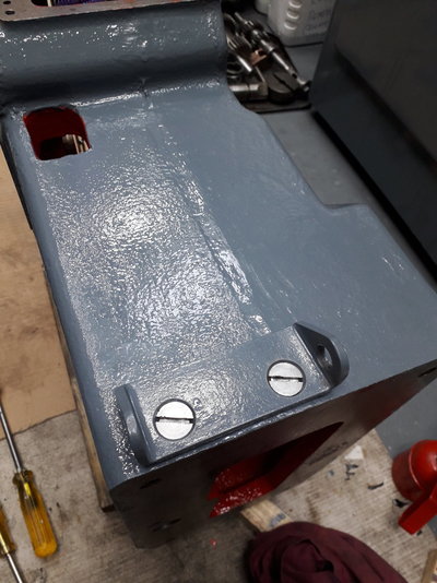
and the motor mounting plate. The pivot bolt is a replacement. The original takes split pins, which broke on disassembly and I don't have replacements:
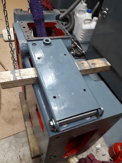
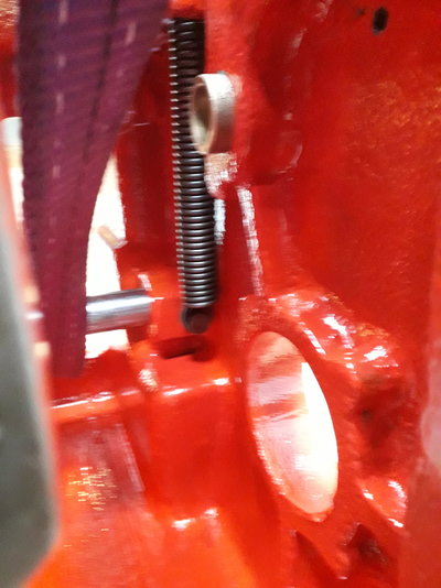
Then the motor plate spring and the tensioning bolt. Once the rest of the internals are fitted, this spring is all but inaccessible.
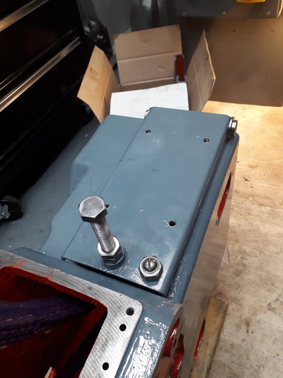
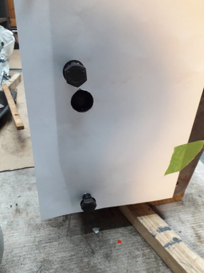
At this stage I took advantage of access to the base to make a template for the location of the hole which I assume provides access in manufacture for tapping the thread for the bolt which holds the spring above and which I'm going to use to pass wires to and from the VFD which will be tucked away in the base. The template will give me a location to drill an access hole in the base.
Starting with an empty main casting, except for the bushings which I didn't disturb as 1) they looked in good nick and 2) they've got a grub screw tapped half in the casting and half in the bush and I didn't fancy my chances of lining them up again if I'd pressed them out.
Step 1, fit the bottom spindle (the fulcrum for the rocking arm) in the body. There is wear on two sides of this so I rotated it 90 degrees to present unworn faces to the arm:


The spindle slides in the left side of the casting ok but needed a tap from a soft blow hammer to drift it into the right side. The ends of this will be visible, unlike its original state where the ends were buried in filler. Then fit the bolt which captures the end of the motor plate spring. This also locks down on the lower spindle and stops it walking out. I needed to use a universal joint on the socket to drive this:

Honestly, it's not as orange as the camera and lamp make it look.
Step 2, lay the main body with the ways down. Makes it easier to fit the motor which will be placed on a horizontal surface. At this point I could just about manhandle the casting though I used the hoist. Once the motor is on it's too heavy for me to lift.

Then fit the pivot bracket for the motor...

and the motor mounting plate. The pivot bolt is a replacement. The original takes split pins, which broke on disassembly and I don't have replacements:

Then the motor plate spring and the tensioning bolt. Once the rest of the internals are fitted, this spring is all but inaccessible.


At this stage I took advantage of access to the base to make a template for the location of the hole which I assume provides access in manufacture for tapping the thread for the bolt which holds the spring above and which I'm going to use to pass wires to and from the VFD which will be tucked away in the base. The template will give me a location to drill an access hole in the base.
RobCox
Member
- Messages
- 443
- Location
- Cambridge, UK
This is the template:
Then install the motor. The bolts are too long to start without tilting the motor slightly, hence doing it horizontally:
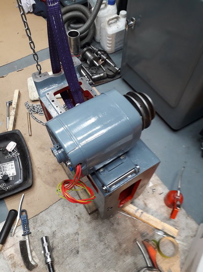
It's not lined up properly, as I found out later, but the pulley it has to line up with is fitted much later. At this stage I fed some wires through the casting to pull the wiring through when I get to the electrics.
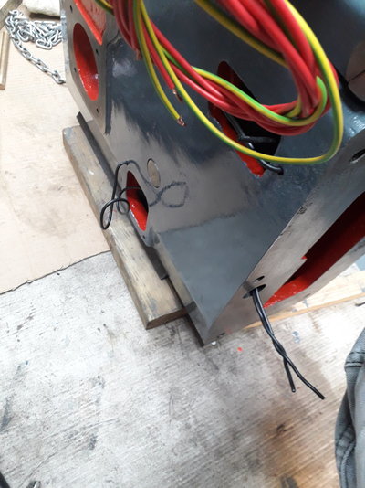
At this point I flipped it back the right way up on some 2 by 4's. The idler gear goes in next, through the side access hatch. The spindle is slid in and the grub screw keeps it all in place.
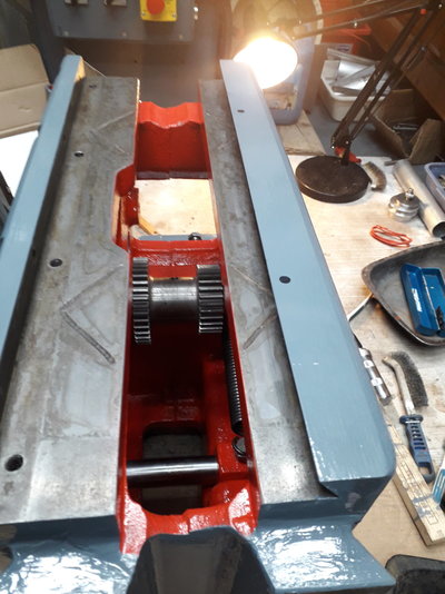
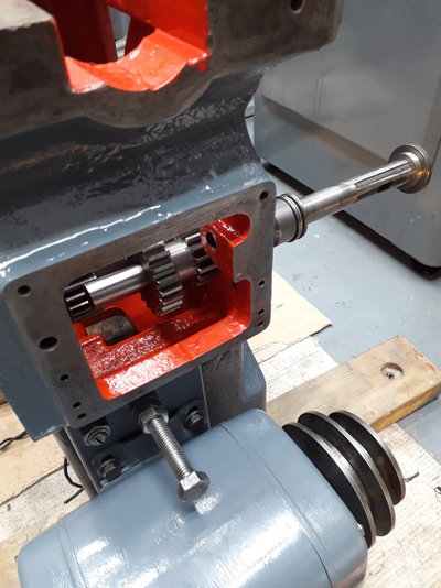
Then the shaft with the high / low speed selector gears. These now slide easily side to side on the keyed spindle, unlike when I got it.
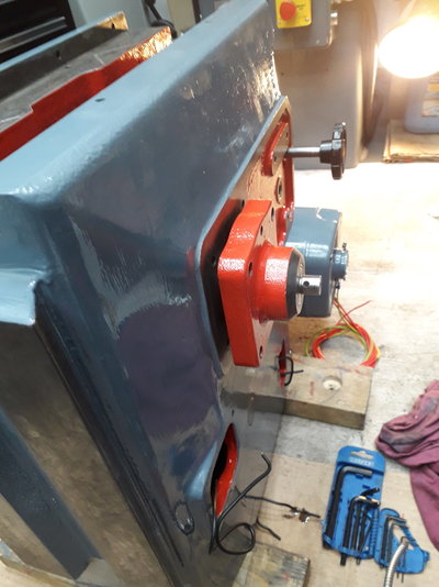
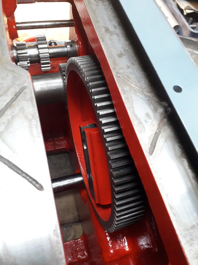
Then the big bull gear. This has to be fed in from above, the spindle poked in from the side and secured to the gear with 4 SHCSs which have to be tightened with nothing to stop the gear moving around, all while you're holding the weight of the gear. Nice. No picture here as I've only 2 hands! The bull gear bracket gets bolted on the casting next and finally this gear is supported:
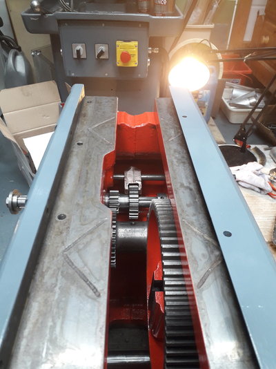
The gear selector rod and fork and the rear access hatch were then fitted to check the gear selection operation. The screw that compresses the detent boll spring is threaded in this rear cover.
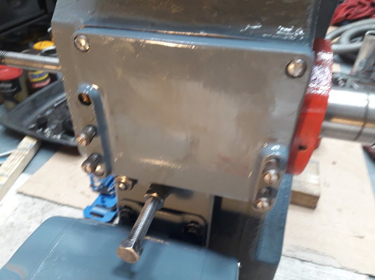

Then install the motor. The bolts are too long to start without tilting the motor slightly, hence doing it horizontally:

It's not lined up properly, as I found out later, but the pulley it has to line up with is fitted much later. At this stage I fed some wires through the casting to pull the wiring through when I get to the electrics.

At this point I flipped it back the right way up on some 2 by 4's. The idler gear goes in next, through the side access hatch. The spindle is slid in and the grub screw keeps it all in place.

Then the shaft with the high / low speed selector gears. These now slide easily side to side on the keyed spindle, unlike when I got it.

Then the big bull gear. This has to be fed in from above, the spindle poked in from the side and secured to the gear with 4 SHCSs which have to be tightened with nothing to stop the gear moving around, all while you're holding the weight of the gear. Nice. No picture here as I've only 2 hands! The bull gear bracket gets bolted on the casting next and finally this gear is supported:


The gear selector rod and fork and the rear access hatch were then fitted to check the gear selection operation. The screw that compresses the detent boll spring is threaded in this rear cover.


RobCox
Member
- Messages
- 443
- Location
- Cambridge, UK
Then onto the side cover with the clutch lever. I assembled the clutch lever and piston while the side housing was off the machine as it was easier to disassemble to deburr and get the action smooth.
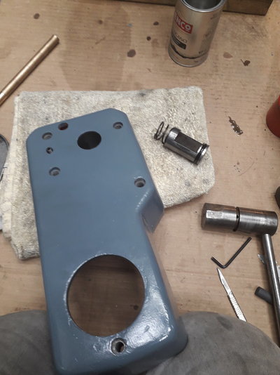
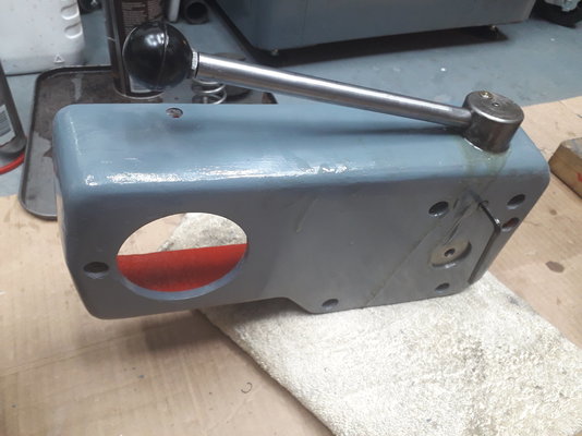
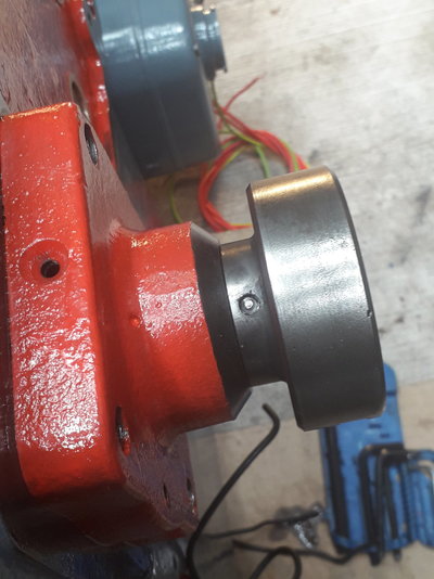
At this stage the grub screws in the piston which adjust the clutch haven't been fitted. Then fit the self-act disc (as the manual calls it). Don't make the mistake (like I did) of fitting the side housing first, as the taper pin which secures this disc is inaccessible once the housing is fitted:
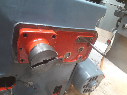
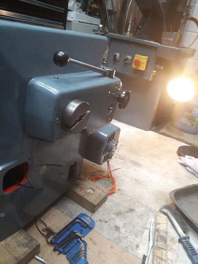
Then before fitting the side housing fit the rod which goes through the gear selector spindle to operate the clutch. Then fit the side housing:
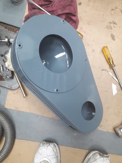
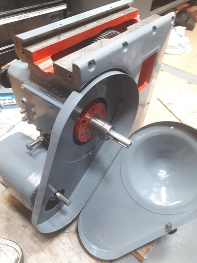
I missed out the bearing bracket earlier which carries the clutch pulley. It supports one end of the gear selector spindle. Now you need four hands again to fit the belt cover and the disc which marries it up to the main body. There's one self tapper that holds these two together, then the disc and cover have to be held up to the body and three screws pass through both and hold them to the main body.
Then the big bearings go in the clutch pulley. I tried pressing them in with a heath robinson arrangement but in the end had more success driving them home with taps of a soft blow around the outer bearing race:
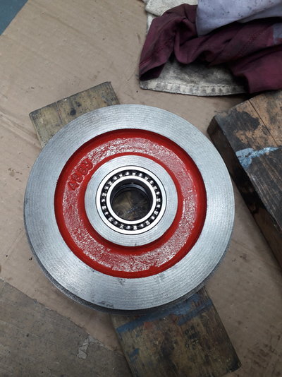
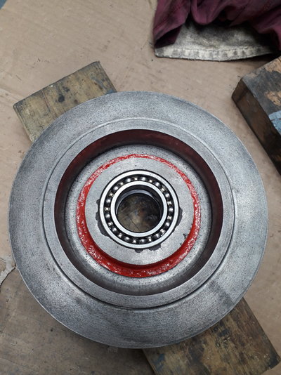
The picture above shows the damage caused when removing the old bearing where the pulley had been bashed with a hammer.


At this stage the grub screws in the piston which adjust the clutch haven't been fitted. Then fit the self-act disc (as the manual calls it). Don't make the mistake (like I did) of fitting the side housing first, as the taper pin which secures this disc is inaccessible once the housing is fitted:


Then before fitting the side housing fit the rod which goes through the gear selector spindle to operate the clutch. Then fit the side housing:

I missed out the bearing bracket earlier which carries the clutch pulley. It supports one end of the gear selector spindle. Now you need four hands again to fit the belt cover and the disc which marries it up to the main body. There's one self tapper that holds these two together, then the disc and cover have to be held up to the body and three screws pass through both and hold them to the main body.


Then the big bearings go in the clutch pulley. I tried pressing them in with a heath robinson arrangement but in the end had more success driving them home with taps of a soft blow around the outer bearing race:


The picture above shows the damage caused when removing the old bearing where the pulley had been bashed with a hammer.
RobCox
Member
- Messages
- 443
- Location
- Cambridge, UK
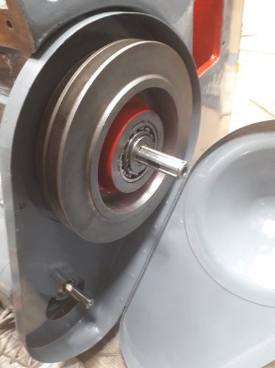
Now put the clutch pulley on. It slid on part way, I persuaded it with gentle thumps for the next bit, then needed an aluminium tube over the centre race driven with a soft blow to get it on to the point where the retaining circlip would fit:
At thois point the motor pulley was fitted and the misalignment became apparent, so on to its face again to adjust the motor alignment.
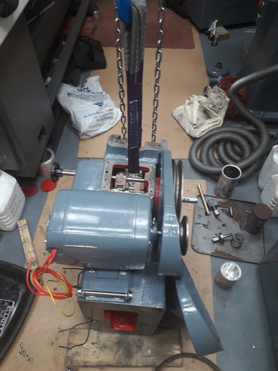
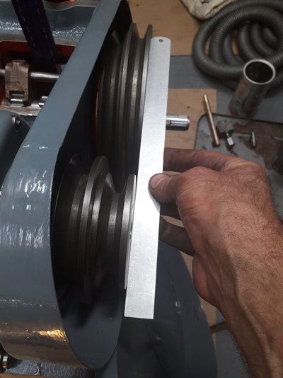
And fit the new belt... except my measurements were wrong. should have ordered a B38, not a B40 . The old one will do for now.
The clutch driven disc goes next, and the pin screwed in both to fix it in place and to give the rod which disengages the clutch something to push on. I remade this pin as the old one had a worn.
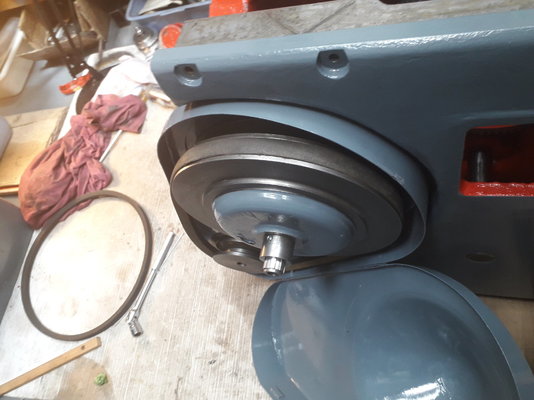
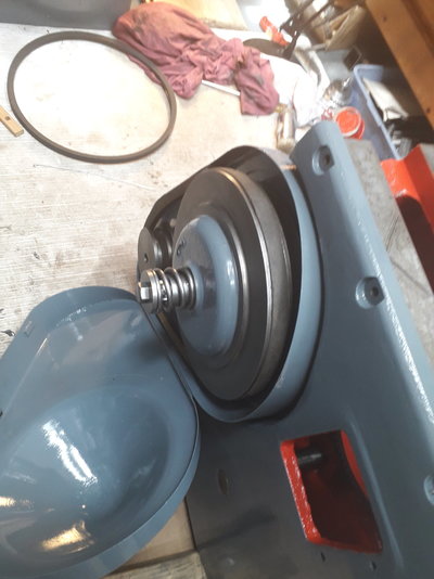
Then the clutch spring and the bolt that holds it all together.
Now the yoke goes in, after I'd drilled and fitted the little tag with the stroke setting dimensions on the side. Liberally slathered in moly grease on the bearing surfaces as it's difficult to get at when assembled. Its a good idea to grease the gears before you fit the yoke, I did so with a paintbrush to spread it around the teeth.
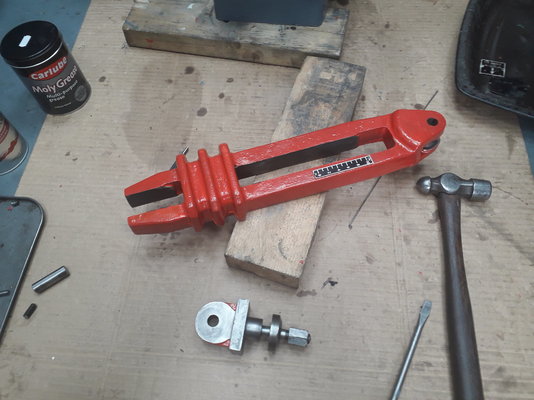
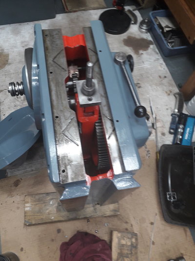
I locktited the stud in the pivot bracket, as @Matthew Tinker suggested. The thread in the pivot bracket is 1/2-12, presumably whit, whereas most of the rest of the machine is UNC (ie 1/2-13). The nut on the top which secures the ram is finer, 1/2-20 or something. And on with the ram, the gib strip and tweak it all up.
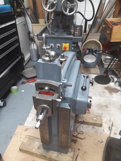
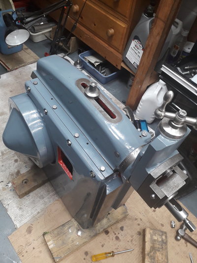
Unlike when I got it, the ram slides really smoothly. Time will tell if it's good when used in anger.
Well, that was a good day's work. Time for bed, said Zebedee...
Rob

At thois point the motor pulley was fitted and the misalignment became apparent, so on to its face again to adjust the motor alignment.


And fit the new belt... except my measurements were wrong. should have ordered a B38, not a B40
 . The old one will do for now.
The clutch driven disc goes next, and the pin screwed in both to fix it in place and to give the rod which disengages the clutch something to push on. I remade this pin as the old one had a worn.

Then the clutch spring and the bolt that holds it all together.

Now the yoke goes in, after I'd drilled and fitted the little tag with the stroke setting dimensions on the side. Liberally slathered in moly grease on the bearing surfaces as it's difficult to get at when assembled. Its a good idea to grease the gears before you fit the yoke, I did so with a paintbrush to spread it around the teeth.


I locktited the stud in the pivot bracket, as @Matthew Tinker suggested. The thread in the pivot bracket is 1/2-12, presumably whit, whereas most of the rest of the machine is UNC (ie 1/2-13). The nut on the top which secures the ram is finer, 1/2-20 or something. And on with the ram, the gib strip and tweak it all up.


Unlike when I got it, the ram slides really smoothly. Time will tell if it's good when used in anger.
Well, that was a good day's work. Time for bed, said Zebedee...
Rob
RobCox
Member
- Messages
- 443
- Location
- Cambridge, UK
I'm using paint from Paragon Paints, superior high temperature enamel paint (apparently). I used it on my mill, 2 grinders and a vice. Bit boring all being the same colour but a 1 litre tin goes a long way and I've stuck with the Bridgeport Blue/Grey.
All applied by brush. I don't have a compressor so spraying is out, plus space inside is limited and I don't want everything oversprayed the same colour! It self levels really well if you don't spread it too thinly.
All applied by brush. I don't have a compressor so spraying is out, plus space inside is limited and I don't want everything oversprayed the same colour! It self levels really well if you don't spread it too thinly.
Brad93
Member
- Messages
- 18,628
- Location
- Essex, United Kingdom
Do you think 2.5L would do a lathe and a mill?I'm using paint from Paragon Paints, superior high temperature enamel paint (apparently). I used it on my mill, 2 grinders and a vice. Bit boring all being the same colour but a 1 litre tin goes a long way and I've stuck with the Bridgeport Blue/Grey.
All applied by brush. I don't have a compressor so spraying is out, plus space inside is limited and I don't want everything oversprayed the same colour! It self levels really well if you don't spread it too thinly.
RobCox
Member
- Messages
- 443
- Location
- Cambridge, UK
Do you think 2.5L would do a lathe and a mill?
I've bought two one litre tins of the enamel in the last couple of years. I've painted my Elliott Model 00 mill, Union tool & cutter grinder, Eagle surface grinder, paramo bench vice and now the Elliott shaper and I've got about half a tin left. Not all those machines got 2 coats. So, if you're going to give both machines 2 coats, you might get away with 1 litre.
2.5 litres will do it easily.
Brad93
Member
- Messages
- 18,628
- Location
- Essex, United Kingdom
That’s awesome will get it bought from paragon. What primer did you use?I've bought two one litre tins of the enamel in the last couple of years. I've painted my Elliott Model 00 mill, Union tool & cutter grinder, Eagle surface grinder, paramo bench vice and now the Elliott shaper and I've got about half a tin left. Not all those machines got 2 coats. So, if you're going to give both machines 2 coats, you might get away with 1 litre.
2.5 litres will do it easily.
RobCox
Member
- Messages
- 443
- Location
- Cambridge, UK
I've used their red oxide and grey primer. Both work, but obviously the red oxide shows through where the enamel hasn't covered so well.
One thing to note - the primer dries really slowly on interior nooks and crannies. So if you paint the inside go sparingly otherwise it could take 2 days to get it really dry. The enamel takes a week or so to get really hard. I put some cardboard on the top of the shaper base so I could store the ram and table on it while I dealt with the main body. When I came to remove them, the pressure had stuck the cardboard and marked the paint. It'll now need a thin touch up coat after a light rubbing down (otherwise the marks will never get removed!).
One thing to note - the primer dries really slowly on interior nooks and crannies. So if you paint the inside go sparingly otherwise it could take 2 days to get it really dry. The enamel takes a week or so to get really hard. I put some cardboard on the top of the shaper base so I could store the ram and table on it while I dealt with the main body. When I came to remove them, the pressure had stuck the cardboard and marked the paint. It'll now need a thin touch up coat after a light rubbing down (otherwise the marks will never get removed!).
RobCox
Member
- Messages
- 443
- Location
- Cambridge, UK
Time to sort out the electrics. The VFD will live in the base. The access hole at the front which used to have a contactor on will get a plate made and a switch fitted. I'm going for a sort of original look to the machine externally so won't be fitting modern pushbuttons to control the VFD like I did for my surface grinder. There is another access hatch at the rear and the original cover has two holes which are suitable for a 20mm flexible conduit fitting and a 16mm cable gland for the mains cable.
First off, I needed to drill a big enough hole in the base to pass the wires through. This has to line up with a hole in the main body and I used the paper template to centre punch the location:
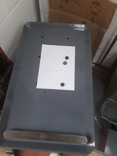
The hole in the casting is 1", the biggest drill I've got is 19mm, so there was a bit of wiggle room there. I don't have a drill press and there's no way this base will fit on the mill (without removing the knee - no way) so I resorted to an old drill stand and portable drill. The drill stand was clamped to the base and the drill passed through the base of the stand to cut the hole:
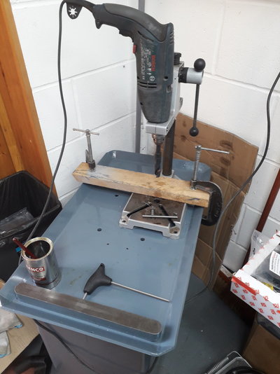
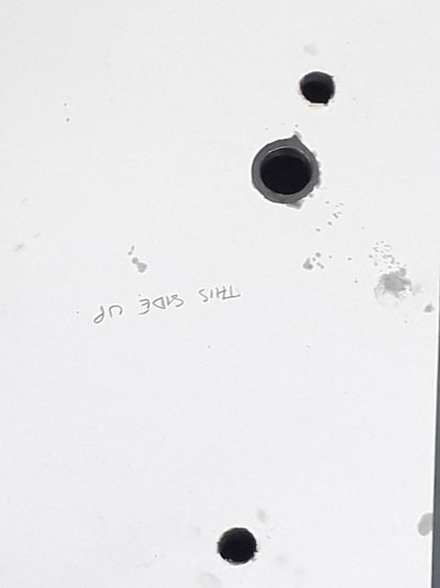
As far as 12mm the Bosch drill works OK. Unfortunately all the drills I have between 12mm and 19mm have morse tapers, so straight in with the 19 it was. This is way more than this hand drill can cope with. Set it in low speed range and modulate the cutting pressure so the drill keeps turning. Cringe. The end result was a nice hole bang in the right place:
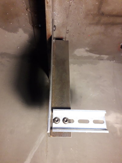
The VFD was now mounted in the base. I bolted a length of L section to one of the reinforcement ribs inside and bolted some DIN rail to that:
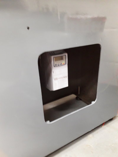
The VFD is then visible when the side panel is removed:
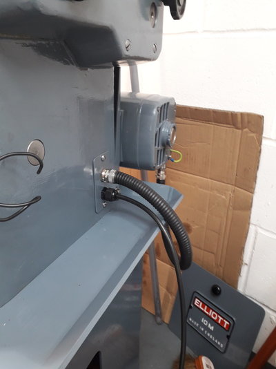
The only externally visible wiring is the mains cable and the conduit to the motor. Here's the finished look:
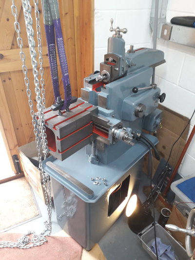
The base got another coat of paint on the top where the cardboard I used to protect it from storing the ram stuck to it and messed it up. Then the shaper was hoisted onto the base, wired up, and the cross slide and table fitted:
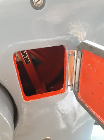
The ram is slid back here to clear the cross slide as it's assembled. A new hinge was cut to length for the side adjustment hatch. The hinge was a 1" wide undrilled piano hinge off ebay:
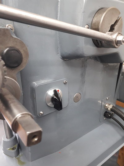
Here's the chicken-head knob used for the on-off switch. The switch was another ebay purchase, NOS 2 way switch with the right sort of feel - a nice satisfying clunk when you turn it on. I made the panel to hold it on the body then needed to turn a bezel to hide the mounting nut. A couple of dimples in the bezel were milled and painted to indicate the on and off positions:
Here it is, almost finished apart from a few finishing touches (ball oilers, information plate, and I'll be putting a modern emergency switch on the side. Safety before looks). I've run it - without a cutter - and all works well:

Now I have to extract the shaper vice from its coat of rust.
Rob
First off, I needed to drill a big enough hole in the base to pass the wires through. This has to line up with a hole in the main body and I used the paper template to centre punch the location:

The hole in the casting is 1", the biggest drill I've got is 19mm, so there was a bit of wiggle room there. I don't have a drill press and there's no way this base will fit on the mill (without removing the knee - no way) so I resorted to an old drill stand and portable drill. The drill stand was clamped to the base and the drill passed through the base of the stand to cut the hole:

As far as 12mm the Bosch drill works OK. Unfortunately all the drills I have between 12mm and 19mm have morse tapers, so straight in with the 19 it was. This is way more than this hand drill can cope with. Set it in low speed range and modulate the cutting pressure so the drill keeps turning. Cringe. The end result was a nice hole bang in the right place:

The VFD was now mounted in the base. I bolted a length of L section to one of the reinforcement ribs inside and bolted some DIN rail to that:

The VFD is then visible when the side panel is removed:

The only externally visible wiring is the mains cable and the conduit to the motor. Here's the finished look:

The base got another coat of paint on the top where the cardboard I used to protect it from storing the ram stuck to it and messed it up. Then the shaper was hoisted onto the base, wired up, and the cross slide and table fitted:

The ram is slid back here to clear the cross slide as it's assembled. A new hinge was cut to length for the side adjustment hatch. The hinge was a 1" wide undrilled piano hinge off ebay:

Here's the chicken-head knob used for the on-off switch. The switch was another ebay purchase, NOS 2 way switch with the right sort of feel - a nice satisfying clunk when you turn it on. I made the panel to hold it on the body then needed to turn a bezel to hide the mounting nut. A couple of dimples in the bezel were milled and painted to indicate the on and off positions:

Here it is, almost finished apart from a few finishing touches (ball oilers, information plate, and I'll be putting a modern emergency switch on the side. Safety before looks). I've run it - without a cutter - and all works well:
Now I have to extract the shaper vice from its coat of rust.
Rob
ronan
Member
- Messages
- 11,399
Which enamel are you using? Brush applied or sprayed?
I have been using cheap 4" rollers for painting recently and am impressed with the finish and the fact you use less paint.
RobCox
Member
- Messages
- 443
- Location
- Cambridge, UK
Thought I'd add to this thread as I was contacted by @GOLDTHORN asking how to remove the swivel head/tool slide assembly from the front of the ram of a 10M. Rather than just reply direct I thought I'd put the information here for all to see.
This is the swivel head to be removed:

The swivel head is locked by the cam, which in turn is locked by a grubscrew. Firstly, loosen off the grubscrew:

The cam can now be loosened to enable the swivel head to um.. swivel. The cam will tighten when rotated one way, but this could be clockwise or anticlockwise depending on which direction it was tightened. Next the swivel head should be rotated 180 degrees:

The dog point screw next to the locking grubscrew keeps the cam from working its way out, so it needs the locknut undoing and it has to be backed out to disengage it from the slot in the cam. The cam can then be driven out - I used a soft blow mallet and a bronze punch:

Once the cam is out, the swivel head pulls out of the front of the ram. This is the boss on the back of the swivel head which fits tightly in the ram. When I first dismantled mine it had burrs from the repeated tightening of the (hardened) cam and some force was needed to get it out. Once the burrs were stoned off reassembly was much easier.

The above picture shows the relief which allows the cam to be withdrawn, hence the need to turn the swivel upside down. For completeness, this is the cam:

This is the swivel head to be removed:
The swivel head is locked by the cam, which in turn is locked by a grubscrew. Firstly, loosen off the grubscrew:
The cam can now be loosened to enable the swivel head to um.. swivel. The cam will tighten when rotated one way, but this could be clockwise or anticlockwise depending on which direction it was tightened. Next the swivel head should be rotated 180 degrees:
The dog point screw next to the locking grubscrew keeps the cam from working its way out, so it needs the locknut undoing and it has to be backed out to disengage it from the slot in the cam. The cam can then be driven out - I used a soft blow mallet and a bronze punch:
Once the cam is out, the swivel head pulls out of the front of the ram. This is the boss on the back of the swivel head which fits tightly in the ram. When I first dismantled mine it had burrs from the repeated tightening of the (hardened) cam and some force was needed to get it out. Once the burrs were stoned off reassembly was much easier.
The above picture shows the relief which allows the cam to be withdrawn, hence the need to turn the swivel upside down. For completeness, this is the cam:
Richie Griffin
New Member
- Messages
- 18
- Location
- DUBLIN Ireland
Hi Rob, you’ve done a fabulous job on the 10M, well done!
I have my eye on a used 10M that’s supposedly ex a school or college. It doesn’t have a vise or a tool holder. Would you be able to share some pics / details of yours? Can you recommend a source for either?
Many thanks,
Richie
I have my eye on a used 10M that’s supposedly ex a school or college. It doesn’t have a vise or a tool holder. Would you be able to share some pics / details of yours? Can you recommend a source for either?
Many thanks,
Richie
RobCox
Member
- Messages
- 443
- Location
- Cambridge, UK
I thought I'd add to this old thread to keep all the info on my shaper in one place, rather than start afresh.
When I've been using the shaper to clean up blocks of stock, if I mic the thickness at each end when two opposing faces have been cleaned up, there's approx 2 thou thickness difference over 4". Not much, but it bugs me and has led me to prefer the mill to the shaper as I can get better accuracy with that. I finally decided to do something about it.
First step was to work out where the error creeps in. I put a DTI on the clapper and swept the ram back and forth over the vice base initially, then eventually pulled the vice off and swept the table. What I found was a slope in the centre of the table travel, but at the extremes of table travel the slope disappeared. My conclusion was that the only thing that could be causing this was wear in the cross slide, so I pulled it off the shaper:

Next I needed to check my references for measuring the cross slide, so first off I gave the surface plate a quick check:

Sweeping the DTI around shows the plate is flat to about 0.0002". Next my chinesium 123 blocks:

These turned out to match to within 0.00015". If I'd dusted these together on the surface grinder, I'm not sure they'd end up much better. The blocks support the vertical ways of the cross slide on the plate high enough to clear the lug for the vertical height nut/gear:

I left the other shaft and gear in as its pinned and the shaft provides something to hold on to. Finally I set the cross slide on the 123 blocks and mapped the wear on the front ways:

The two sets of figures are the measurements with the cross slide orientated with the lug at the back and front, the 123 blocks staying in the same place, to try and average out any accumulated errors. After this, I marked out areas that I figured would need more or less scraping, did a crude step scrape before bluing up for the first time:

The result was pretty much what I'd expected. From here, repeated passes were done trying to bring the corners down evenly as these should be unworn (the milling marks from manufacture were still visible) and should have been in the correct plane with respect to the vertical ways. Here it is a bit further on - the blue is a little bit thick:

When I reached the stage below, I stopped as I figured it was good enough for now and I didn't want to remove too much material if I'd changed the plane of the ways. The insides of the centres are still low, but gives me a reference of where things were if more adjustments were required:

After the ways and the surface plate were cleaned up I set it, scraped ways down, on the plate and swept the vertical ways with a DTI. Turns out I'd got lucky and not scraped it wonky. I checked the back of the ways next. These were flat, except for the last inch where they stood less than a thou proud. I decided to reassemble the machine first before deciding to mess with these to see if I'd made things better.
I clamped a parallel onto the table to give me a smooth surface to run a dial indicator across:

The blue line shows the point on the table travel where the flatness deviates by about a thou. In the middle it's flat. The other extreme, with about 0.75 thou error, is 130mm / 5" away:

I'm happy enough with that for now, I'm calling that a win. I'll try a couple of projects on the shaper before doing any more adjustments.
When I've been using the shaper to clean up blocks of stock, if I mic the thickness at each end when two opposing faces have been cleaned up, there's approx 2 thou thickness difference over 4". Not much, but it bugs me and has led me to prefer the mill to the shaper as I can get better accuracy with that. I finally decided to do something about it.
First step was to work out where the error creeps in. I put a DTI on the clapper and swept the ram back and forth over the vice base initially, then eventually pulled the vice off and swept the table. What I found was a slope in the centre of the table travel, but at the extremes of table travel the slope disappeared. My conclusion was that the only thing that could be causing this was wear in the cross slide, so I pulled it off the shaper:
Next I needed to check my references for measuring the cross slide, so first off I gave the surface plate a quick check:
Sweeping the DTI around shows the plate is flat to about 0.0002". Next my chinesium 123 blocks:
These turned out to match to within 0.00015". If I'd dusted these together on the surface grinder, I'm not sure they'd end up much better. The blocks support the vertical ways of the cross slide on the plate high enough to clear the lug for the vertical height nut/gear:
I left the other shaft and gear in as its pinned and the shaft provides something to hold on to. Finally I set the cross slide on the 123 blocks and mapped the wear on the front ways:
The two sets of figures are the measurements with the cross slide orientated with the lug at the back and front, the 123 blocks staying in the same place, to try and average out any accumulated errors. After this, I marked out areas that I figured would need more or less scraping, did a crude step scrape before bluing up for the first time:
The result was pretty much what I'd expected. From here, repeated passes were done trying to bring the corners down evenly as these should be unworn (the milling marks from manufacture were still visible) and should have been in the correct plane with respect to the vertical ways. Here it is a bit further on - the blue is a little bit thick:
When I reached the stage below, I stopped as I figured it was good enough for now and I didn't want to remove too much material if I'd changed the plane of the ways. The insides of the centres are still low, but gives me a reference of where things were if more adjustments were required:
After the ways and the surface plate were cleaned up I set it, scraped ways down, on the plate and swept the vertical ways with a DTI. Turns out I'd got lucky and not scraped it wonky. I checked the back of the ways next. These were flat, except for the last inch where they stood less than a thou proud. I decided to reassemble the machine first before deciding to mess with these to see if I'd made things better.
I clamped a parallel onto the table to give me a smooth surface to run a dial indicator across:
The blue line shows the point on the table travel where the flatness deviates by about a thou. In the middle it's flat. The other extreme, with about 0.75 thou error, is 130mm / 5" away:
I'm happy enough with that for now, I'm calling that a win. I'll try a couple of projects on the shaper before doing any more adjustments.
Smouser
Member
- Messages
- 1,101
- Location
- Amesbury, Wiltshire, UK
Excellent work as always!I thought I'd add to this old thread to keep all the info on my shaper in one place, rather than start afresh.
When I've been using the shaper to clean up blocks of stock, if I mic the thickness at each end when two opposing faces have been cleaned up, there's approx 2 thou thickness difference over 4". Not much, but it bugs me and has led me to prefer the mill to the shaper as I can get better accuracy with that. I finally decided to do something about it.
First step was to work out where the error creeps in. I put a DTI on the clapper and swept the ram back and forth over the vice base initially, then eventually pulled the vice off and swept the table. What I found was a slope in the centre of the table travel, but at the extremes of table travel the slope disappeared. My conclusion was that the only thing that could be causing this was wear in the cross slide, so I pulled it off the shaper:
View attachment 412489
Next I needed to check my references for measuring the cross slide, so first off I gave the surface plate a quick check:
View attachment 412490
Sweeping the DTI around shows the plate is flat to about 0.0002". Next my chinesium 123 blocks:
View attachment 412491
These turned out to match to within 0.00015". If I'd dusted these together on the surface grinder, I'm not sure they'd end up much better. The blocks support the vertical ways of the cross slide on the plate high enough to clear the lug for the vertical height nut/gear:
View attachment 412492
I left the other shaft and gear in as its pinned and the shaft provides something to hold on to. Finally I set the cross slide on the 123 blocks and mapped the wear on the front ways:
View attachment 412493
The two sets of figures are the measurements with the cross slide orientated with the lug at the back and front, the 123 blocks staying in the same place, to try and average out any accumulated errors. After this, I marked out areas that I figured would need more or less scraping, did a crude step scrape before bluing up for the first time:
View attachment 412495
The result was pretty much what I'd expected. From here, repeated passes were done trying to bring the corners down evenly as these should be unworn (the milling marks from manufacture were still visible) and should have been in the correct plane with respect to the vertical ways. Here it is a bit further on - the blue is a little bit thick:
View attachment 412497
When I reached the stage below, I stopped as I figured it was good enough for now and I didn't want to remove too much material if I'd changed the plane of the ways. The insides of the centres are still low, but gives me a reference of where things were if more adjustments were required:
View attachment 412498
After the ways and the surface plate were cleaned up I set it, scraped ways down, on the plate and swept the vertical ways with a DTI. Turns out I'd got lucky and not scraped it wonky. I checked the back of the ways next. These were flat, except for the last inch where they stood less than a thou proud. I decided to reassemble the machine first before deciding to mess with these to see if I'd made things better.
I clamped a parallel onto the table to give me a smooth surface to run a dial indicator across:
View attachment 412501
The blue line shows the point on the table travel where the flatness deviates by about a thou. In the middle it's flat. The other extreme, with about 0.75 thou error, is 130mm / 5" away:
View attachment 412502
I'm happy enough with that for now, I'm calling that a win. I'll try a couple of projects on the shaper before doing any more adjustments.
I enjoyed learning how you measured and checked to find out where the problem was.
Now that you have practised and with @Pete. battery powered Biax (whatever fancy thing that is) I really feel you should come and do my Invicta shaper

I bet it is three or four times worse than your Elliott!


