You are using an out of date browser. It may not display this or other websites correctly.
You should upgrade or use an alternative browser.
You should upgrade or use an alternative browser.
I need to fix a broken APC UPS (inverter)
- Thread starter julianf
- Start date
Wendelspanswick
Member
- Messages
- 6,471
Funnily enough I went through our pile of recovered inverters yesterday as we had one fail and I needed a short term replacement. Unfortunately none of them are as big as your one, lots of 1500's and similar.£140, with the additional battery pack. But, as ive found out above, APC units are a total gamble - no schematics or anything available when they die.
There is a large redundant UPS in one of the local hospitals that is surplus to requirements, no one can be bothered to shift it out so I will have a look next time I am on site.
julianf
Member
- Messages
- 8,813
- Location
- devon, uk
That seems like a bargain, is the first unit scrap then?
I was going to try some more to fix it, once the 8kva turned up (that i could familiarise myself with) however, the front panel control is required by somoene else, so it looks like it will be broken.
Ill probably give the logic board to somone i know with the same unit, keep the batteries, and scrap the main board. Or waste my time watching no end of youtube videos as to how to turn them into stand-alone sine wave inverters.
Why - have you got any ideas for it? (again, its less the control panel at present)
Kayos
Gone......
- Messages
- 9,682
- Location
- North Lincolnshire
I've been thinking along your lines but with PV cells, as when the sun is brightest, no one is home and I'd rather use it than feed it back to the grid.
It's only a thought mind, I'm doing lots of working out before I hand over my hard earned for the panels
It's only a thought mind, I'm doing lots of working out before I hand over my hard earned for the panels
julianf
Member
- Messages
- 8,813
- Location
- devon, uk
Funnily enough I went through our pile of recovered inverters yesterday as we had one fail and I needed a short term replacement. Unfortunately none of them are as big as your one, lots of 1500's and similar.
There is a large redundant UPS in one of the local hospitals that is surplus to requirements, no one can be bothered to shift it out so I will have a look next time I am on site.
Thank you for looking - appreciated.
The one noone can be bothered to shift - sounds like one of those jobs where lots of people would happily move it (indeed, i probably would) however, without being on the approved contractors list etc...
julianf
Member
- Messages
- 8,813
- Location
- devon, uk
I've been thinking along your lines but with PV cells, as when the sun is brightest, no one is home and I'd rather use it than feed it back to the grid.
It's only a thought mind, I'm doing lots of working out before I hand over my hard earned for the panels
My original plan with the engine was to claim ROCS, but, whilst that is still technically possible, the additional paperwork now costs more than the ROCS would be salable for. I did look into, at one point, companies who would buy your power for the 3.6p / unit wholesale price, but even then it wasnt really viable, so the whole plan just stalled. I would be running into the same issue with production being higher than load, and noone wanting to recompense me for the export.
Which is even worse in this case, as the exported power would have a unit cost to me.
However, with a large enough UPS, the production will track load, and the ups can smooth out any overload. I could disconnect from the grid, and that will be that.
Im not sure that the numbers work just on the electricity, but we will get about double the kW output from the engine in recovered heat, and have the aded benefit of being able to suffer outages. This is also gearing up to a longer term plan of moving to a site that initially wont have a grid connection at all...
Solar panels are a separate irritation for me, as i still have the G83 GTI sitting in a box somewhere (that was initially acquired to couple to the engine). I figured i could look out for some cheap panels (as they come up in ones and twos fairly often)
However, in my naivety, what i did not realise is that the panels need to be matched to the inverter, and that you cant just grow a system in an organic fashion with cheap cast-offs : (
As my GTI is 2.5kw, which is more power than we generally need, and i wont be getting FITs, its never seemed like a good idea to shell out £600 or so on the panels that id need to match the GTI.
I guess i should sell the unit really.
Come to think of it, i also have a wind turbine 5kw PMA under the stairs also. Fat lot of good its doing under there....
At least with this 8kva unit i should finally be able to get somthing working! : )
Shox Dr
Chief Engineer to Carlos Fandango
- Messages
- 17,866
- Location
- East Yorkshire
My original plan with the engine
Sorry! Engine? (im lost)
julianf
Member
- Messages
- 8,813
- Location
- devon, uk
Sorry! Engine? (im lost)
Another UPS, coming my way (this one works, but i am having to pay for it) -
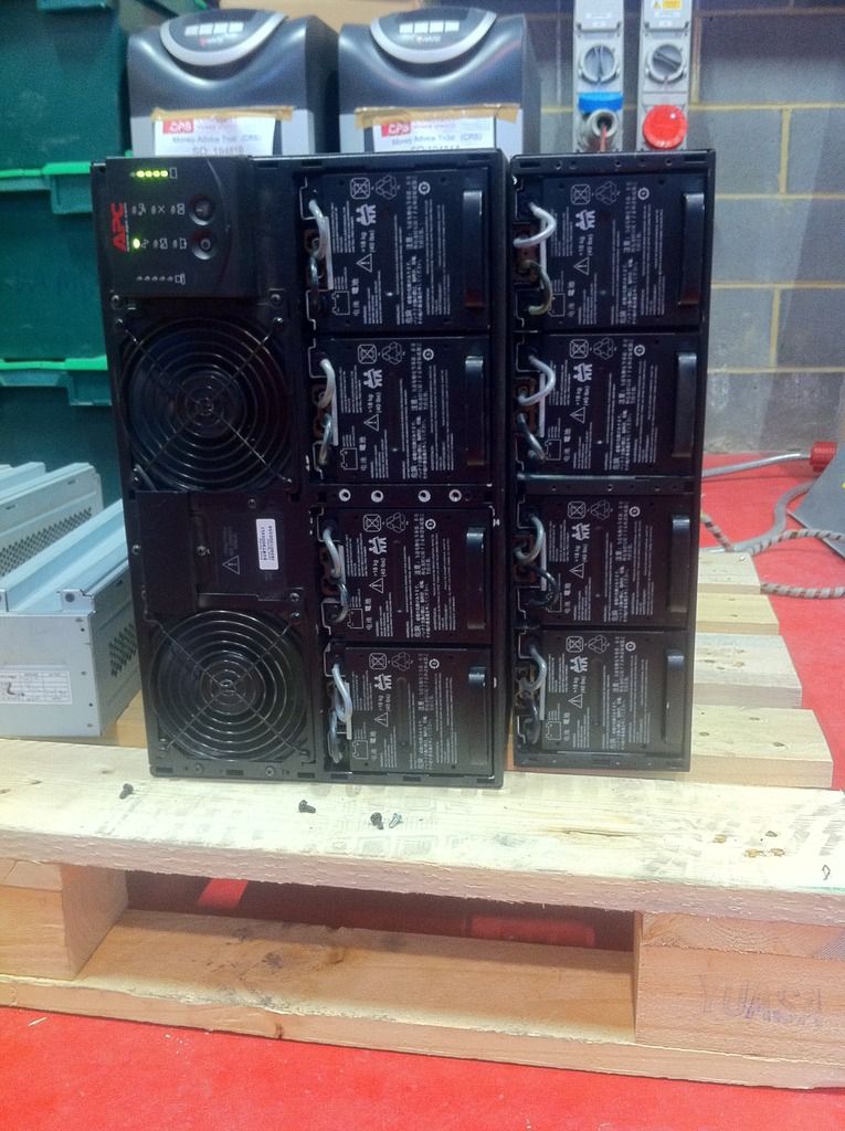
8kva, and has the additional add-on battery pack. You would not want to put your tongue across those terminals!
Why do i want one?
Firstly, to keep the cnc machine running through brown outs etc.
Secondly, i have a 1950s single cylinder lister. Ive been trying to get that hooked up to the house electrics for some time, but have never been able to work out a way to not just cause issues (a grid tie inverter was my first plan, but then the engine wont track the load. i then thought about current shunts and servos, but never got around to it)
Anyhow, a large ups between the generator and the house will allow for short term overloads (ie pulling more power than the generator can supply) without needing the generator on full power all the time.
Right, so here is the board im looking at -
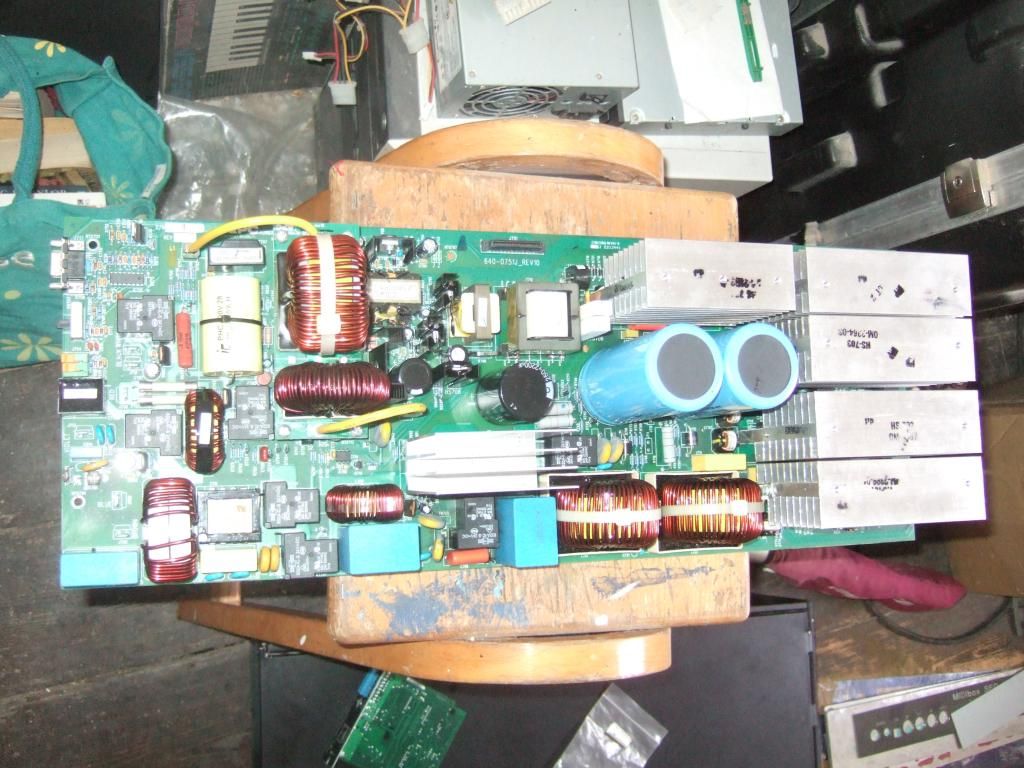
The AC comes in at the bottom left hand corner. You can see the terminals marked "Blue" and "Brown"
As i understand it, the two 24v dc relays to the right of the terminals are the ones that turn on and off the mains input, according to if the batteries are present / healthy.
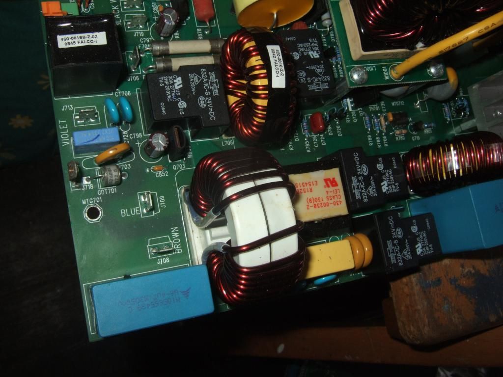
Here is a view of the underneath of the board. I think that the pathway is along the edge of the board (ie from top left of the photo, rightwards)
You can see the flux where the cap was soldered in just under 2/3rds of the way across the photo (from the left) - at the end of the y-shaped thinner trace thats closest (but not close) to the top left corner.
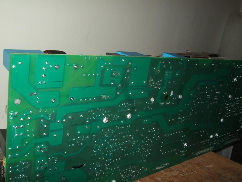
Back to the top again, and moving further across - the two relays again -
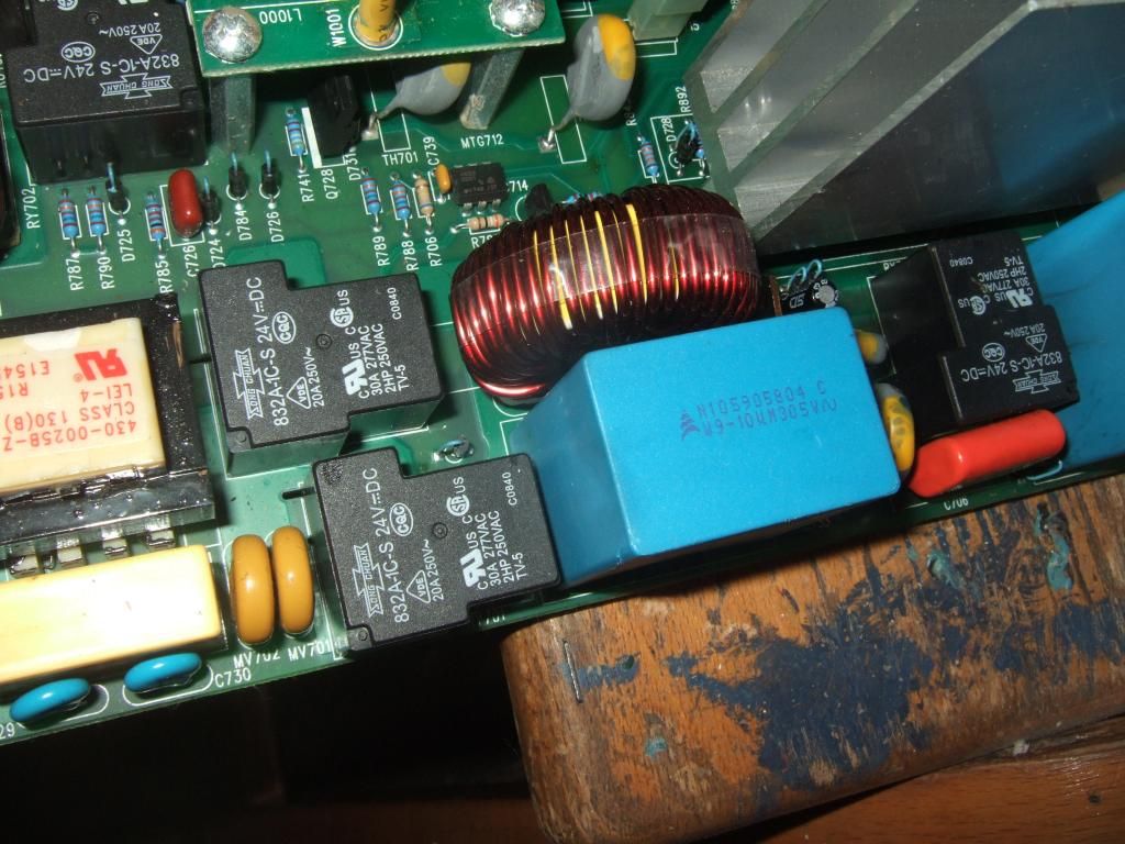
And now onto where the damage was -
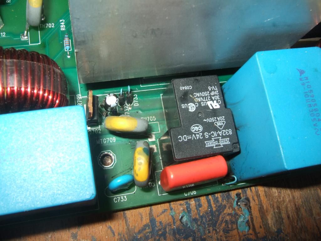
Im told that the small electrolytic ruptured, and spewed its guts over some distance. We're talking the one between the TO-220 package transistor and D732 / D733.
I have not powered up the board at all yet - need to find some space on the table. I wonder if the TO-220 package cooked the electrolytic some, however, replacing the electrolytic (with the incorrect value mind!) has certainly not cured the issue. Ive since been told that the correct part is a 33uF 35V, and the part currently fitted is a 47u 25v.
One final shot of the brains of the machine -
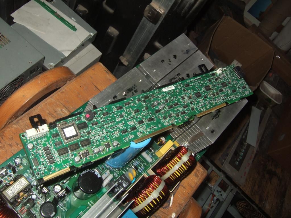
You can see its a much fancier board, plugging into the one im working on using its edge connector (female sockets are both covered, and just round the back of the heatsinks, which is why you cant see them in the shot)
Right, so here is the board im looking at -

The AC comes in at the bottom left hand corner. You can see the terminals marked "Blue" and "Brown"
As i understand it, the two 24v dc relays to the right of the terminals are the ones that turn on and off the mains input, according to if the batteries are present / healthy.

Here is a view of the underneath of the board. I think that the pathway is along the edge of the board (ie from top left of the photo, rightwards)
You can see the flux where the cap was soldered in just under 2/3rds of the way across the photo (from the left) - at the end of the y-shaped thinner trace thats closest (but not close) to the top left corner.

Back to the top again, and moving further across - the two relays again -

And now onto where the damage was -

Im told that the small electrolytic ruptured, and spewed its guts over some distance. We're talking the one between the TO-220 package transistor and D732 / D733.
I have not powered up the board at all yet - need to find some space on the table. I wonder if the TO-220 package cooked the electrolytic some, however, replacing the electrolytic (with the incorrect value mind!) has certainly not cured the issue. Ive since been told that the correct part is a 33uF 35V, and the part currently fitted is a 47u 25v.
One final shot of the brains of the machine -

You can see its a much fancier board, plugging into the one im working on using its edge connector (female sockets are both covered, and just round the back of the heatsinks, which is why you cant see them in the shot)
Do you see the wisps of carbon on that blue capacitor? I would check that relay for burned contacts
regards
Dave
Masterofnone
New Member
- Messages
- 24
- Location
- Bucks, UK
If you ever look at it again it might be worth checking Q702 and D732,D733 if they are connected to the blown cap if the cap went short then it could easily have taken the transistor with it.
The 25v replacement cap is not suitable. Replacing with a higher voltage 50v will be ok but 25v may well have a very short very short life before going bang/catching fire. I doubt the value will be too critical in that application.
The new cap is connected correctly with regard to polarity?
There are fuses on the board next to each other F701 and F??? so it may be worth lifting one end and checking their continuity.
There may be more but without being able to read the board it is difficult to see. It does appear to have quite a lot of input circuit protection though.


