Arvorsteve
New Member
- Messages
- 7
- Location
- sussex
Hi Eddie and thanksHello and welcome to the Forum !
Since it is the same model of welder and has similar faults, I think it would be OK to just carry on with this thread, so please go ahead here.
Here's a similar inverter repair thread, by the same OP - @The_Motorcyclist - which ended in success:
Parweld XTT182DV no power
I have an XTT182DV inverter set, which is currently not showing any signs of life. A preliminary investigation is showing that I am getting AC voltage to the first pair of rectifiers and when the DC side of the rectifiers is disconnected from the main PCB there is 240V DC. When the DC side of...www.mig-welding.co.uk
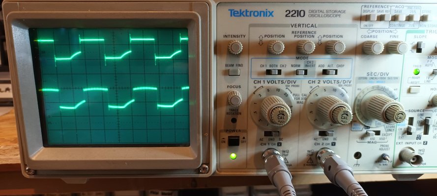
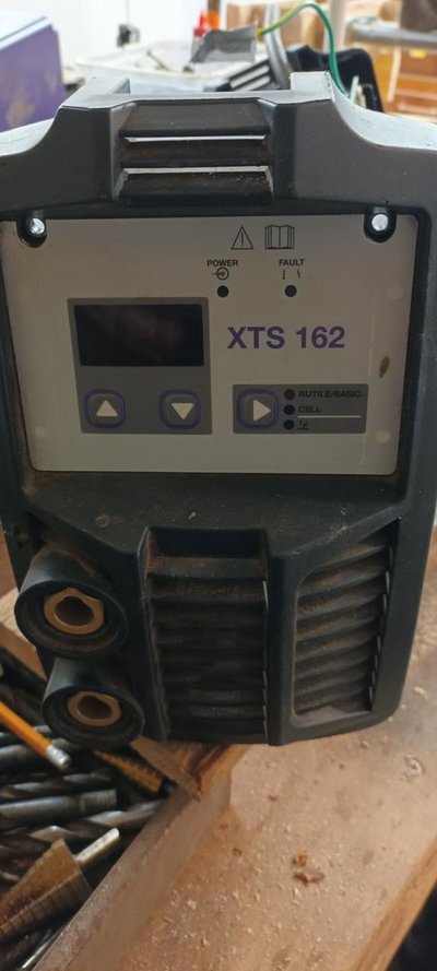
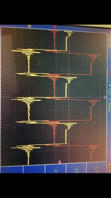
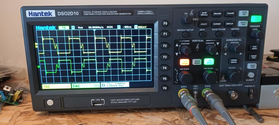
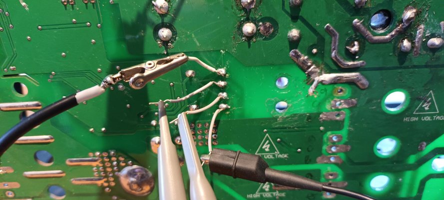
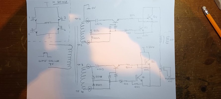
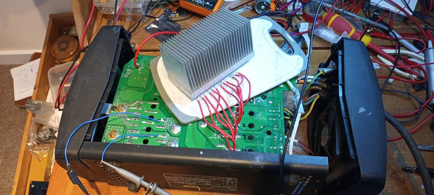
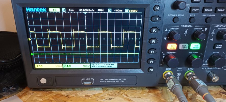
Please see photos of my IGBT gate drive signals and the front of the model I have.
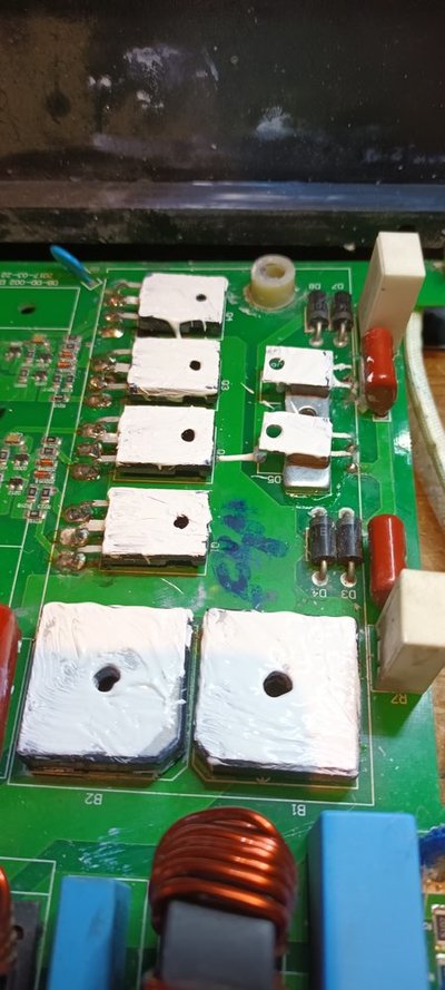
I have replaced the IGBT's and the welder ran for about 10 seconds off load ( after replacing the trashed start up thermistor) until one of the IGBT's failed again. I am wondering if the gate signals are the issue. There are basically 4 x FGH40N40 IGBT's, configured as two pairs, with their collectors and emitters paralleled up for current handling.
Both gate drive signals are in phase and appear to be at about 57Khz and 22V, although the square waves are not too good and there are a few overshoot spikes on the edges, that might have caused damage?
I would be interested in seeing a PDF of that circuit that The Mororcyclist posted, although I don't think it's for the model I have.
I like the idea of running the IGBT's up on a lower voltage current limited supply as someone else suggested. I think I might try that when the replacement IGBT's arrive, but I am reluctant to do that until I get some comments back about the gate drive signals.
Thanks guys.
