mike os
just a little insane.....
- Messages
- 9,777
- Location
- North Wales
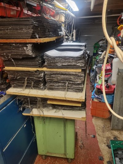
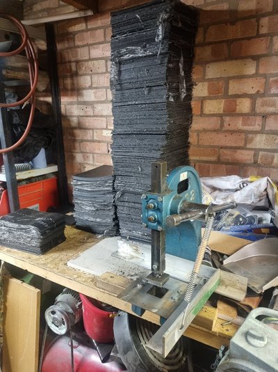
Fetish?I can't get my head around this, what does the knife holder go in, and why do you want ten thousand felt squares?

Fetish?I can't get my head around this, what does the knife holder go in, and why do you want ten thousand felt squares?

Ahh - it's the .stl file that I was on about (the original design), not the G code.
I will post files up later but for now how do I get a files to CMC? <--CNC??

No all info greatfully received.Ahh - it's the .stl file that I was on about (the original design), not the G code.
Edit:
I'm not sure if you're asking a more fundamental question:
Once you have a CAD design (be it 2D or 3D) one needs to run CAM software where you describe how you would like to machine / cut / etc. the design - In the case of a router, for example:
* What diameter cutter you will be using
* How fast do you want to feed it
* What depth of cut, etc.
* How big is the stock?
* In what order do you want to machine it?
etc. etc.
Once all this is sorted, you will have the tool paths needed to machine the part.
The next step is to 'post process' these to produce the G Code that will run on your specific machine.
All of this is possible within the 'Manufacturing' workspace in Fusion360 (or loads of other programs).
Apologies if we've ended up in granny/eggs territory

Try these...it won't help with use of files but it's how I have refined the setup over time.I can't get my head around this, what does the knife holder go in, and why do you want ten thousand felt squares?
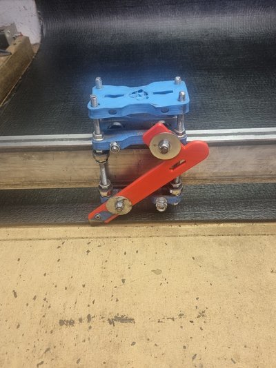
It also has a tag for the blade on the opposite side to the photo of the red one.
Will upload STL later. I need to look for it.
I guess that would be possible but I have had one 3D printed part last over 10000 squares so in all honesty it's not a great issue.From the original picture of how the 3DP has failed, it looks as if the metal blade is being forced into the plastic print by the cutting pressure, splitting it like a log.
Could you incorporate a metal insert into the print at 90 degrees to the blade (looking end-on, the blade plus insert would be T-shaped) so the load is spread over a much wider area? Even a single circular metal pin through the print at the position of maximum stress might spread the load enough to lengthen its life.


managed to save as a stepfile https://www.dropbox.com/s/90qsw77cfgl4pym/UtilityKnife(Holder,Clamp)(swamitized!)-B5 v1.step?dl=0No all info greatfully received.
Will upload STL later. I need to look for it.
Possibly and possibly quicker for me to Bridgeport it. But the main aim was to get my **** into gear and learn to use the CNC. Sadly, the need to get the squares finished took precedence over using it as a live project. Plus illness in much of the family and Dad catheter playing up again meant a straight choice of going and relaxing for a few days. I took the relaxing.Quickest way to make that, cut it out of steel or alu sheet. 10 mins with drill, grinder and tin snips. Thick 3-5mm layer for the frame. Thin, same thickness as blade for the pocket, tig it in place. 3rd peice just to screw clamp

I was not worried about the 10 model limit or the lack of rapids BUT I now see fusion wants you to pay to export to DXF files lolDon't worry about it, I don't think it's much use to you at the moment (other than for curiosity's sake).
Think of the CAM stage as the equivalent step to the slicer on your 3D printing.
It'll be easier to do the CAM if all the faces are flat and true (which you can guarantee by starting from scratch - if you've got the dimensions, it's quick to draw up anyway), and it will need some modification to make the internal corners machinable.
Something like this:
View attachment 378328
(F360 model, roughly drawn by eye attached - feel free to grab it if it's of any use to you. Blade recess has 4mm clearances to suit ~3mm cutter)
Edit to add missing machining relief & another edit to add link to the CAM Post processor for F360 / UCCNC
I sort of guessed from Devs previous reply that was the case. But thought fusion might twigg that instead of wanted me to pay for full version only to find I could not do.it anyway. LolYour trying to export a body which needs a 3d output file.
You can only export a sketch as a dxf.
managed to save as a stepfile
But @MattH has confirmed I can't do that. Now I am confused..The main problem I would think is whether the F360 output is compatible with the OP CNC.
Much better to create a 3 view and export DXF, import that into CNC software and create toolpaths

