Dr.Al
Forum Supporter
- Messages
- 2,507
- Location
- Gloucestershire, UK
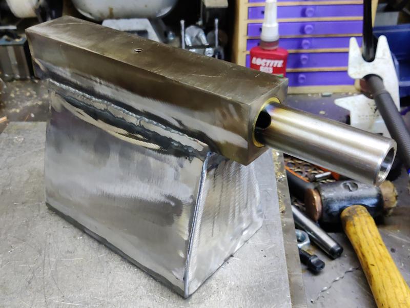
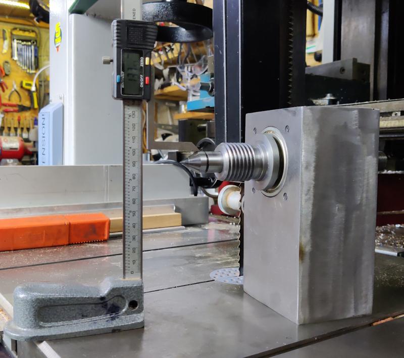
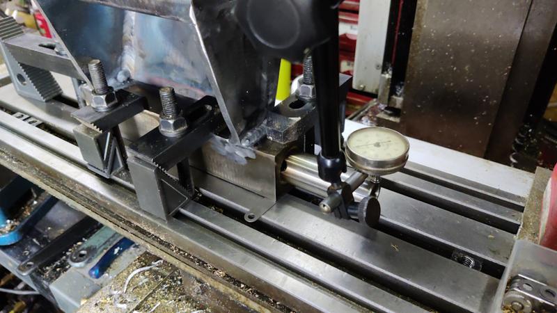
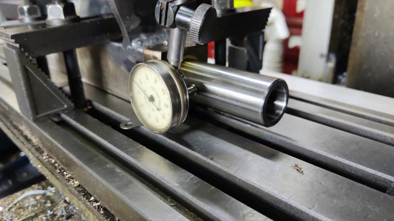
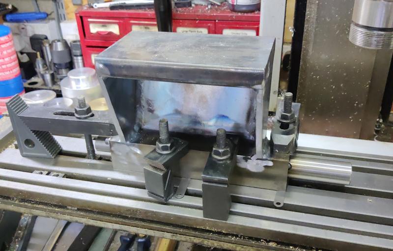
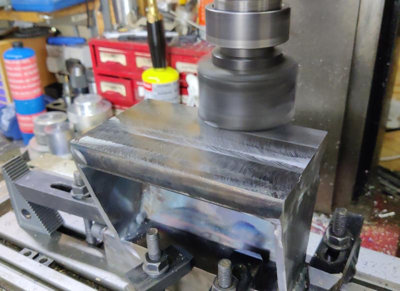
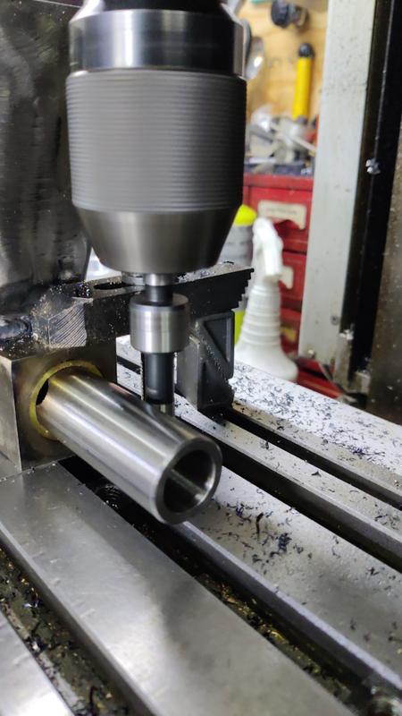
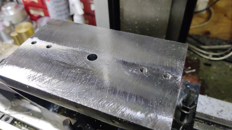
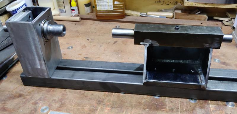
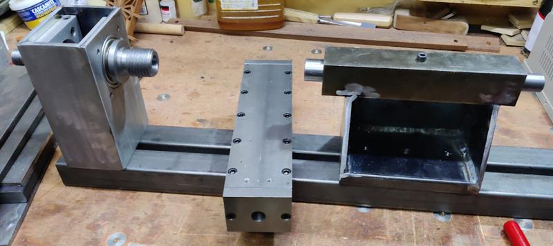
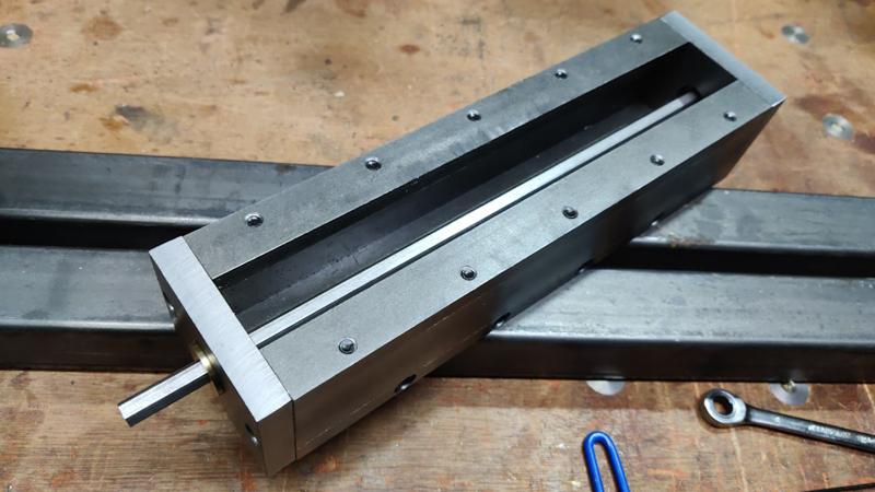
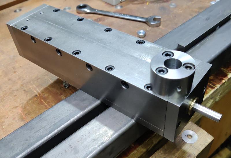
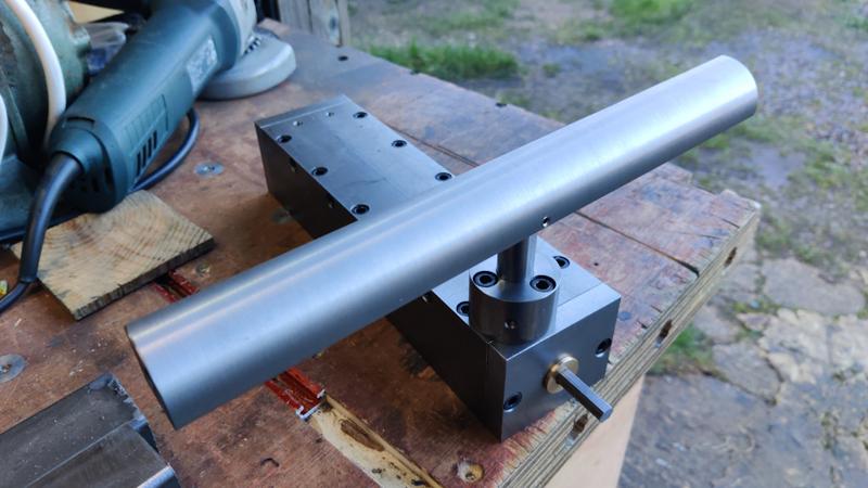
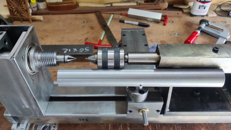
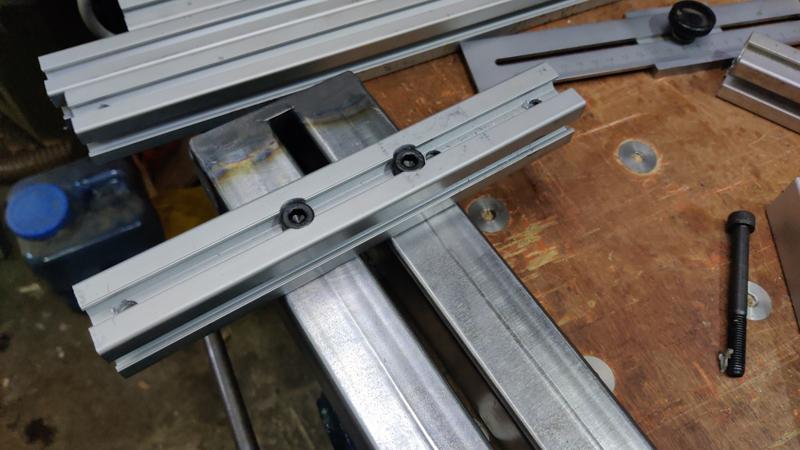
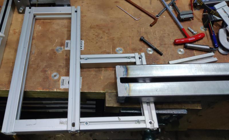
The next big job for the tailstock was to make the frame that connects the tailstock to the bed and ensures it stays parallel with the bed axis and at the right centre height.
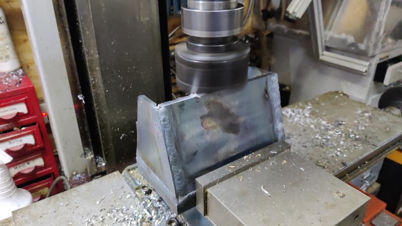
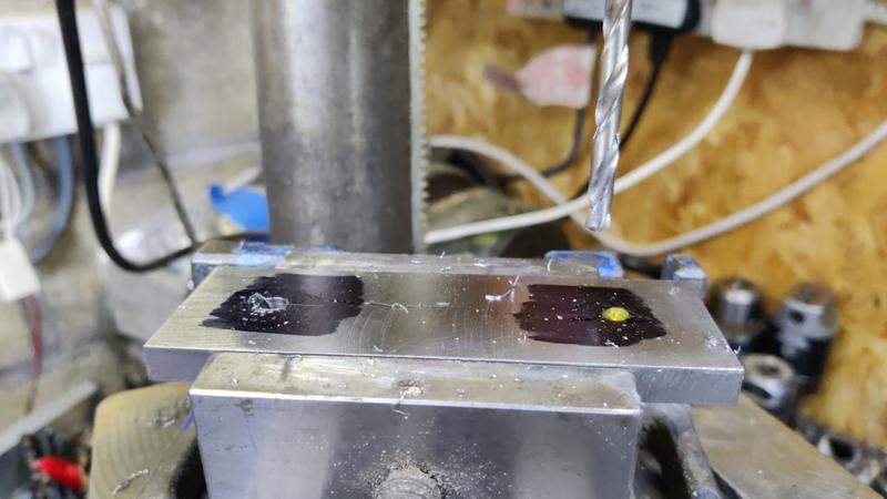
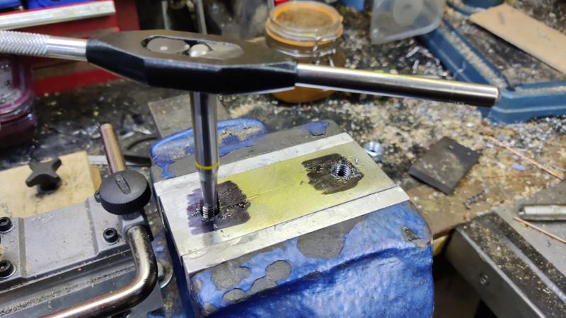
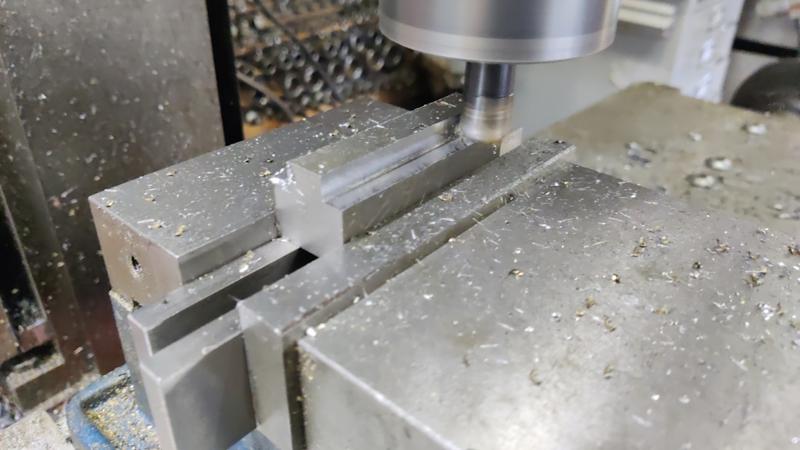
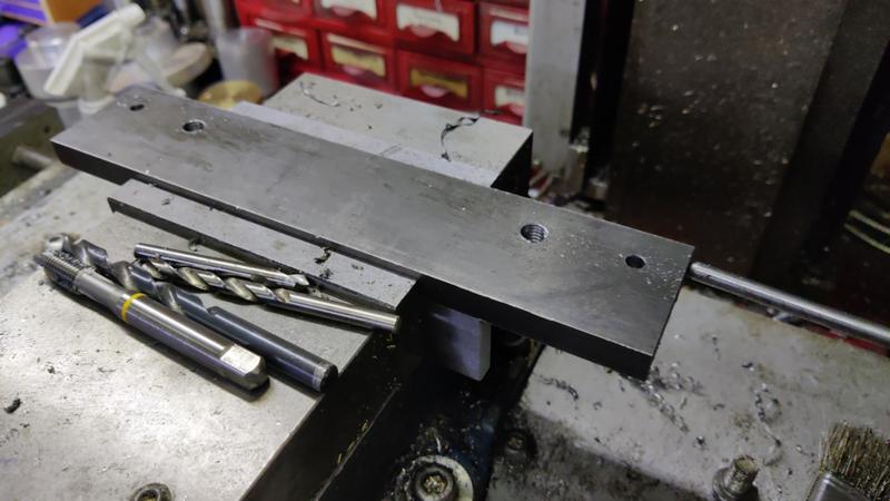
I've decided to make the base of the bed out of some 20 mm thick hot rolled steel. This is a lot more substantial than it really needs to be, but it means I don't have to bother with weld nuts (the steel is thick enough to tap directly) and it gives me a lot of room for adjustment: I'll build the frame over size and then mill down the bottom of the base plate to get the centre height right. If I made it out of 6 mm steel and had to take 2 mm off to get the centre height right then the plate would be getting a bit thin.
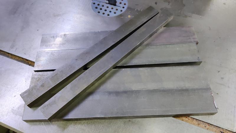
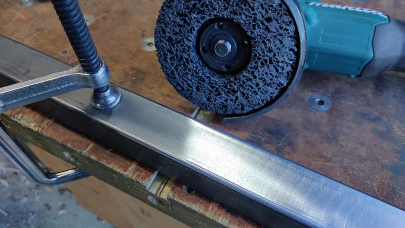
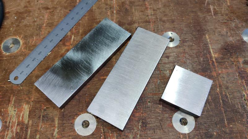
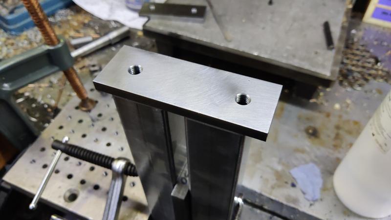
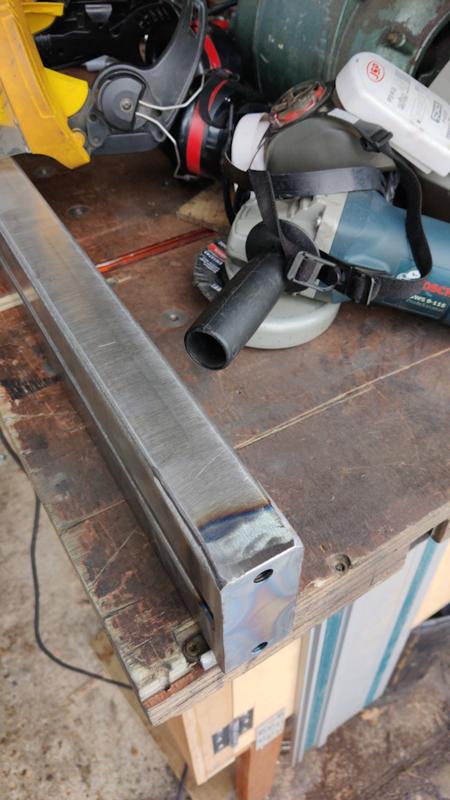
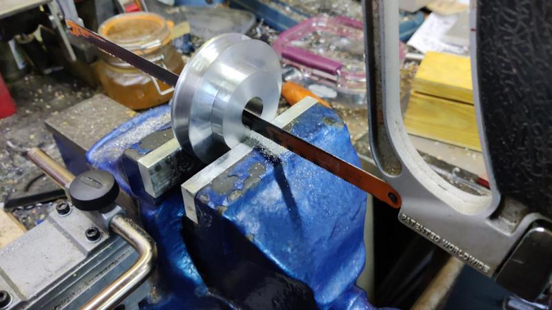
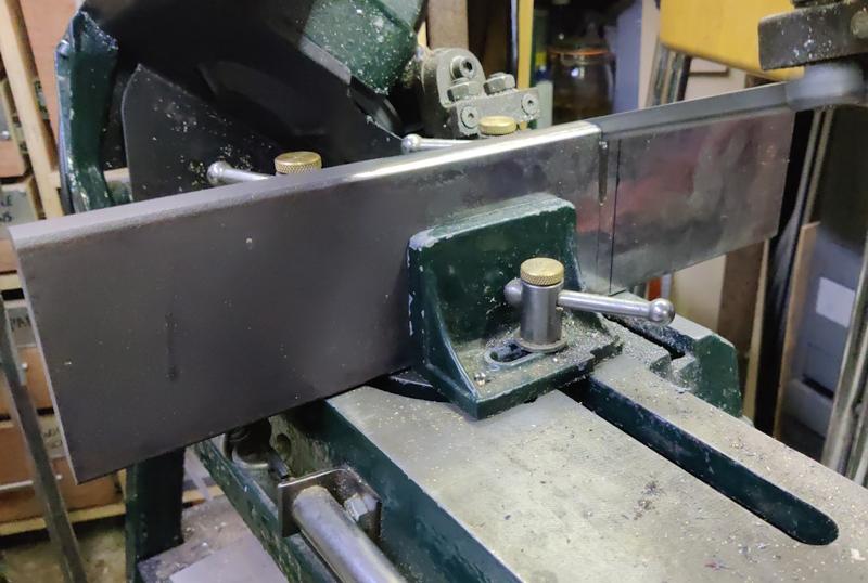
I've got one piece of 20 mm × 100 mm hot rolled steel with some thick mill scale on it, so the first job was to clean off a lot of that mill scale (firstly with a non-woven preparation wheel and then with an 80 grit flap disc). I then cut a section off with the horizontal bandsaw:
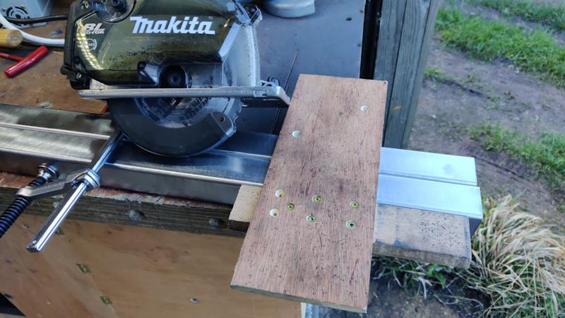
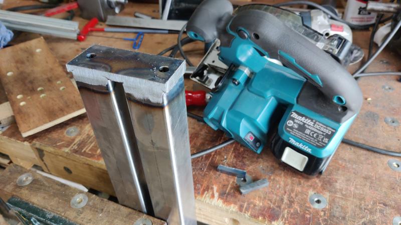
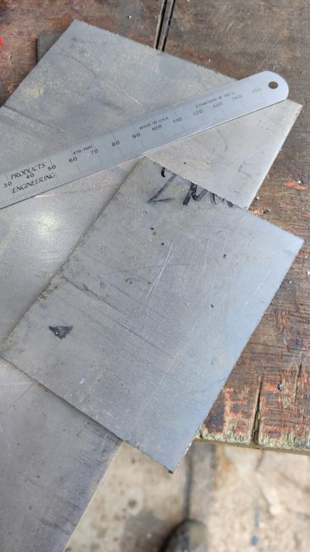
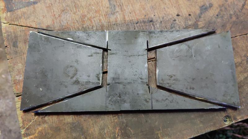
To make the ends of the tailstock frame, I got a bit of 6 mm stock and cut it into bits using the angle grinder with a cut-off disc (it seemed a bit small to easily hold for use of the metal cutting circular saw):
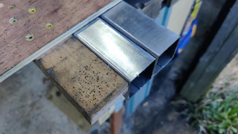
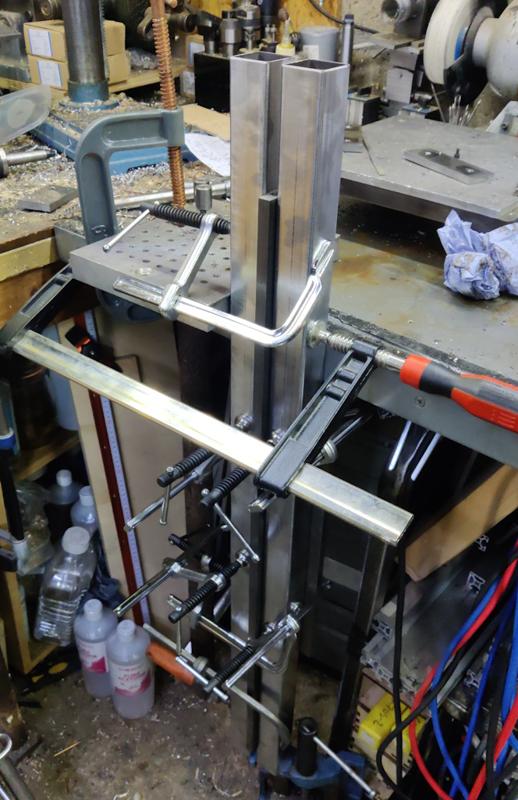
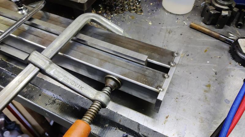
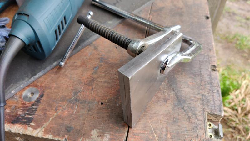
I then cleaned up the faces with a non-woven wheel and then clamped the two pieces together and used a flap disc to make them the same shape:
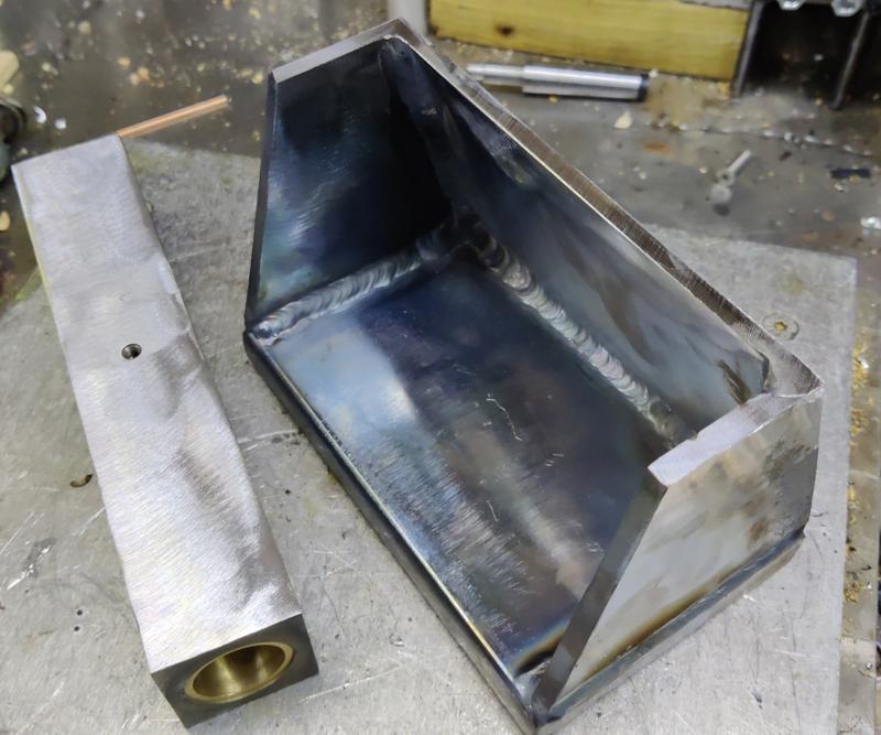
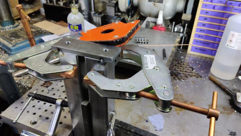
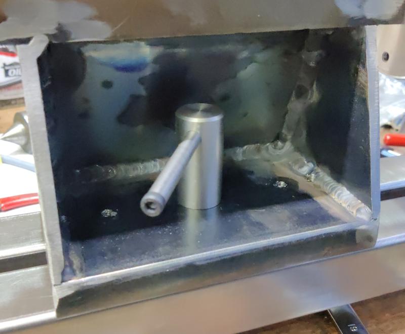
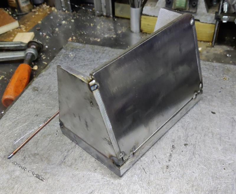
With that done, I tack-welded all the base bits together:
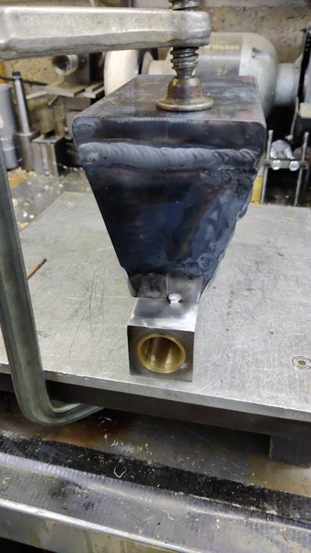
I then decided to pre-heat them a bit with a MAPP gas torch:
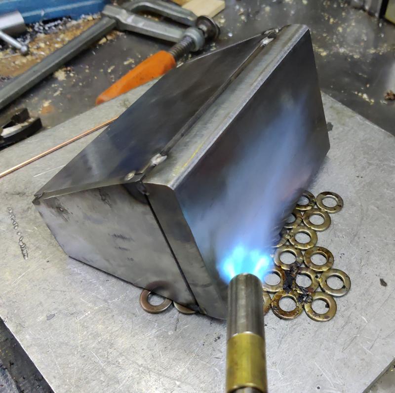
I've no idea whether that was necessary or helpful, but I've never tried to TIG weld anything this thick before and I figured it couldn't hurt. If I had any sense, I probably would have stick welded it, but I enjoy TIG welding a lot more (and I'm a lot better at it).
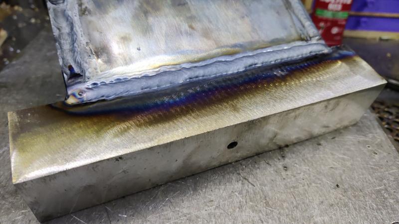
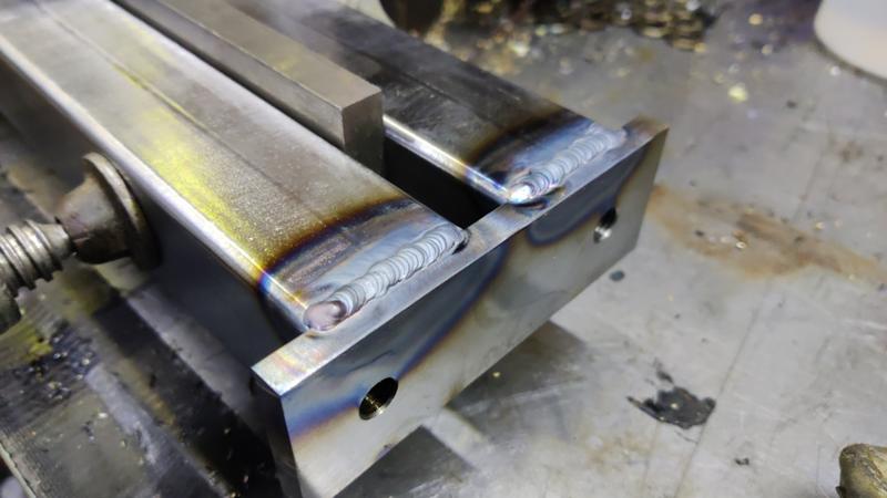
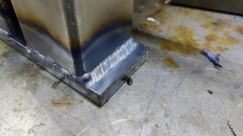
Once I'd got bored of pre-heating, I turned the TIG welder up to the maximum current (210 A) and went for it:
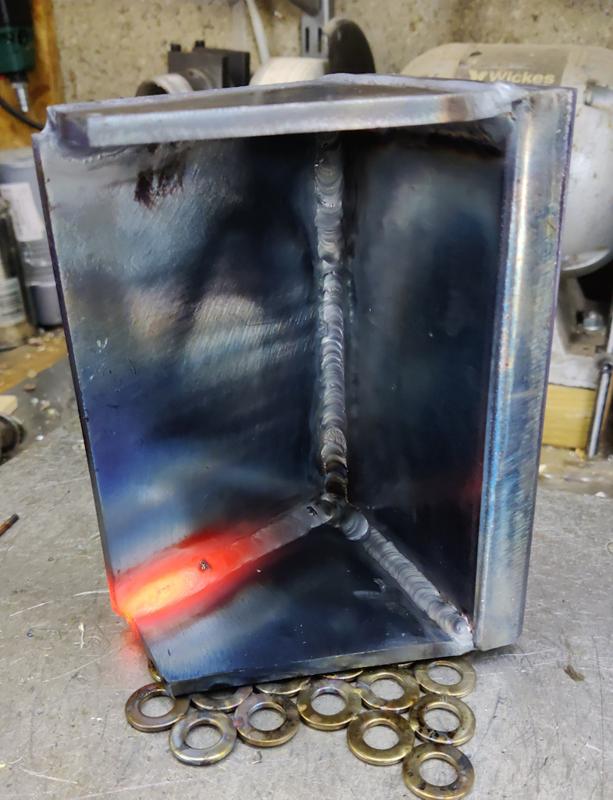
By the end of the weld, it was quite hard to hold the TIG torch due to the heat coming off the tailstock base! I'll now leave it to cool down.
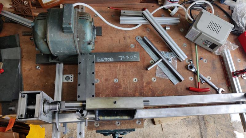
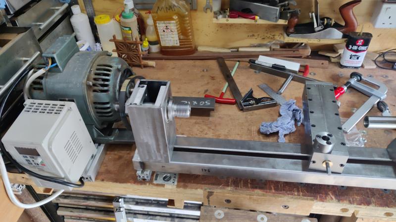
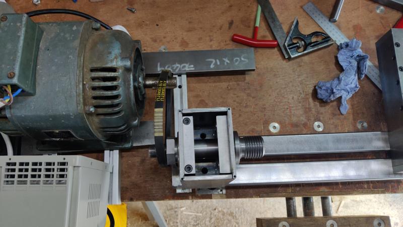
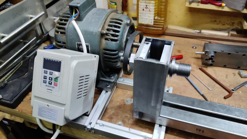
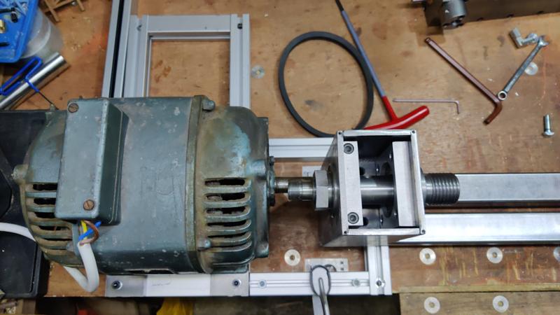
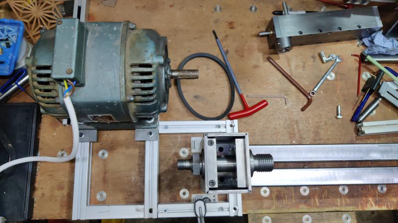
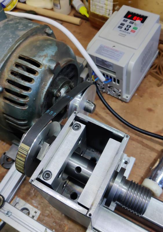
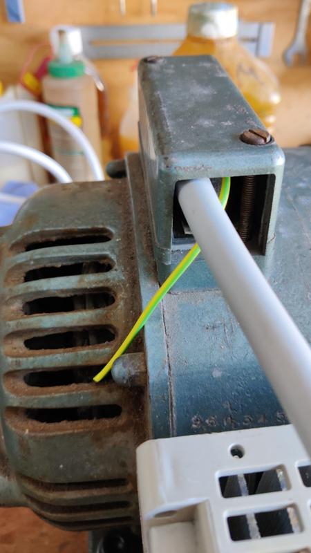
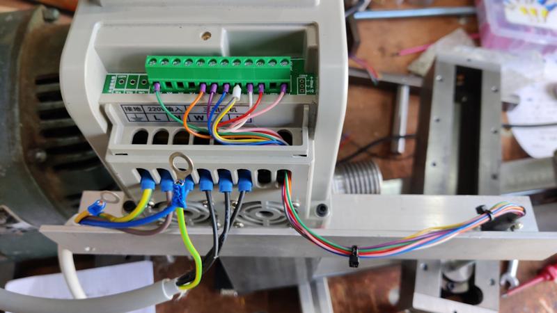
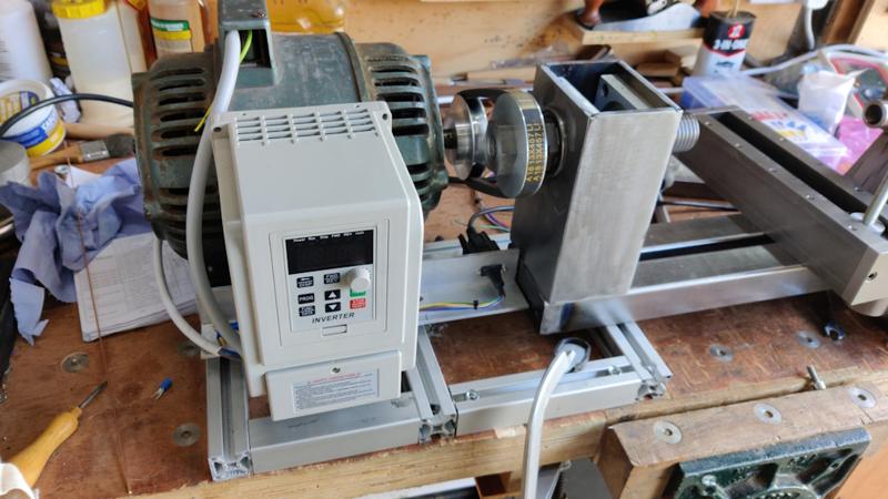
I said at the start of this project that I was going to try to do it without buying anything. Well, I've failed! I've got a couple of single phase motors that I could have chosen for the power source, but then an old 1.1 kW (1.5 hp) three phase motor popped up on ebay relatively locally. I was the only bidder, so I picked it up for the auction starting price £10. To run it, I need an inverter, but I found a 2.2 kW one brand new for £53, which wasn't too bad considering. Hopefully they'll both work! All being well, this should be much better than a single phase motor as I can more easily get variable speed operation.
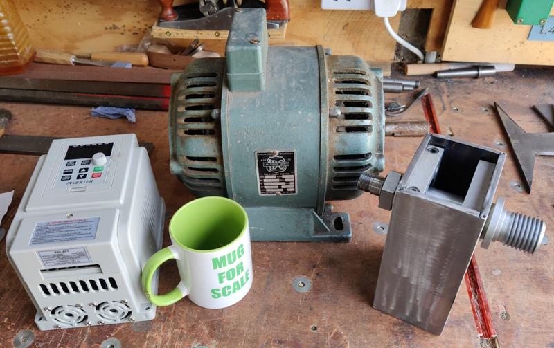
It's a big old beast (and somewhat out of proportion to the lathe if I'm honest), but there should be plenty of power, even when running it at reduced speed.
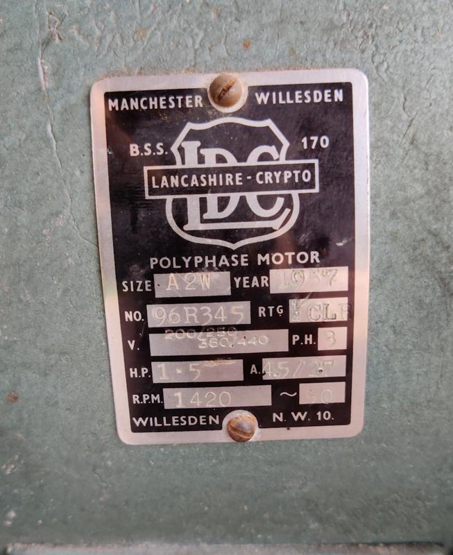
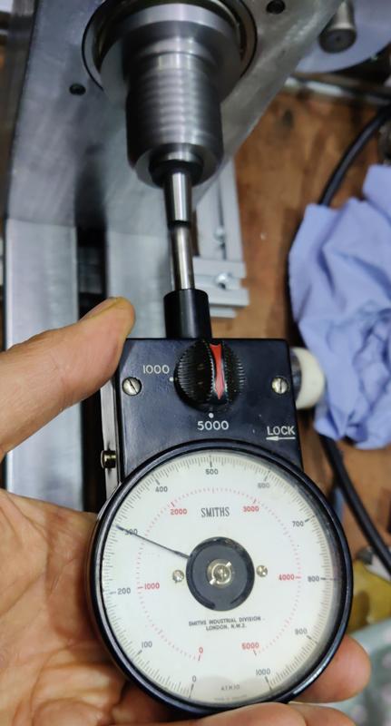
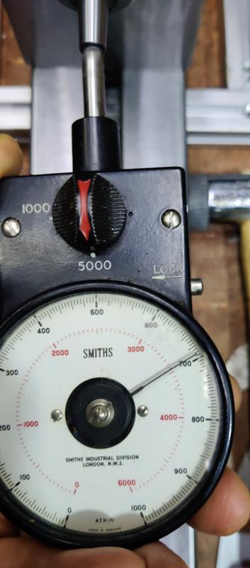
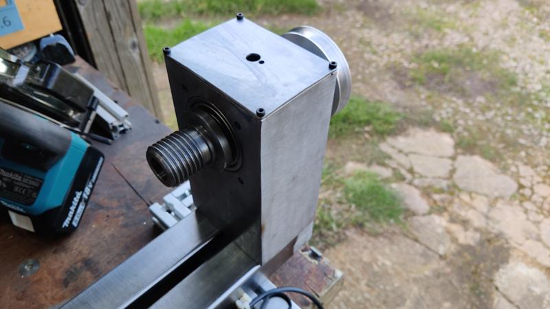
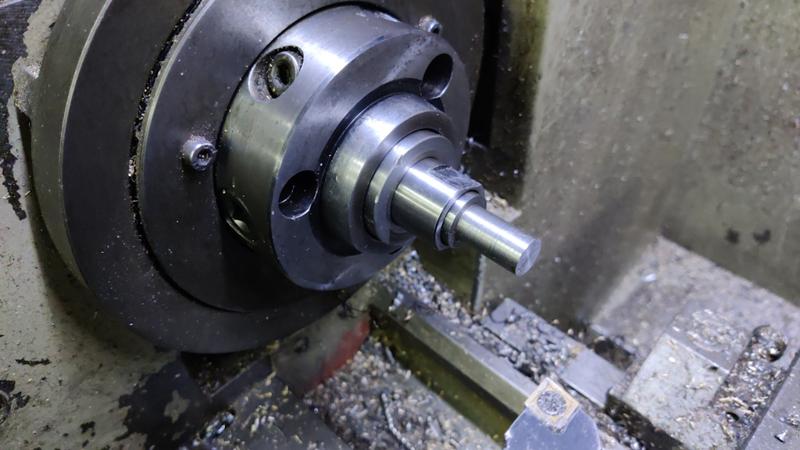
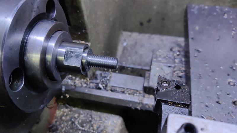
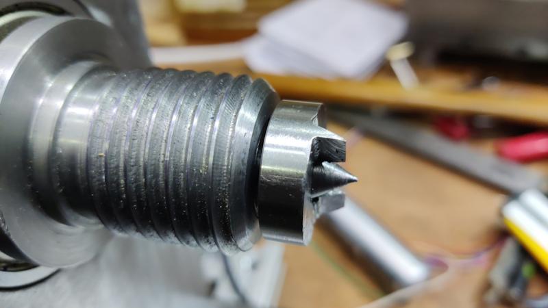
It's a 4-pole motor and hence only runs at 1420 rpm. Ideally I would have gone for a 2-pole one for the higher speeds that seems to be preferable for spindle work on a wood lathe (from what I've read). However, as it's such a powerful motor, I should be able to gear it up with careful choice of pulleys and that should bring the spindle speed up to where it needs to be. If I can figure out a way to modify the spindle to have a 19 mm (3/4") pulley mount, then I'll be able to swap pulleys between the motor and the spindle and pick between a 2:1 ratio and a 1:2 ratio with only two pulleys. The variable speed drive should sort out the rest, so that seems like the ideal thing to aim for. The only challenge will be sorting out the spindle's pulley-mounting thread, which is currently M20×1.5. If I could reduce it to M18×1.5, then I could just skim off the existing threads and start again. However, the through bore is 15 mm so that might be getting a bit thin. What I'll probably try to do is cut it as M19×1.5 and just do my best to align the new threads with the old ones. That's a challenge for another day though...
I've decided to make the base of the bed out of some 20 mm thick hot rolled steel. This is a lot more substantial than it really needs to be, but it means I don't have to bother with weld nuts (the steel is thick enough to tap directly) and it gives me a lot of room for adjustment: I'll build the frame over size and then mill down the bottom of the base plate to get the centre height right. If I made it out of 6 mm steel and had to take 2 mm off to get the centre height right then the plate would be getting a bit thin.
I've got one piece of 20 mm × 100 mm hot rolled steel with some thick mill scale on it, so the first job was to clean off a lot of that mill scale (firstly with a non-woven preparation wheel and then with an 80 grit flap disc). I then cut a section off with the horizontal bandsaw:

To make the ends of the tailstock frame, I got a bit of 6 mm stock and cut it into bits using the angle grinder with a cut-off disc (it seemed a bit small to easily hold for use of the metal cutting circular saw):

I then cleaned up the faces with a non-woven wheel and then clamped the two pieces together and used a flap disc to make them the same shape:

With that done, I tack-welded all the base bits together:

I then decided to pre-heat them a bit with a MAPP gas torch:

I've no idea whether that was necessary or helpful, but I've never tried to TIG weld anything this thick before and I figured it couldn't hurt. If I had any sense, I probably would have stick welded it, but I enjoy TIG welding a lot more (and I'm a lot better at it).
Once I'd got bored of pre-heating, I turned the TIG welder up to the maximum current (210 A) and went for it:

By the end of the weld, it was quite hard to hold the TIG torch due to the heat coming off the tailstock base! I'll now leave it to cool down.
I said at the start of this project that I was going to try to do it without buying anything. Well, I've failed! I've got a couple of single phase motors that I could have chosen for the power source, but then an old 1.1 kW (1.5 hp) three phase motor popped up on ebay relatively locally. I was the only bidder, so I picked it up for the auction starting price £10. To run it, I need an inverter, but I found a 2.2 kW one brand new for £53, which wasn't too bad considering. Hopefully they'll both work! All being well, this should be much better than a single phase motor as I can more easily get variable speed operation.

It's a big old beast (and somewhat out of proportion to the lathe if I'm honest), but there should be plenty of power, even when running it at reduced speed.

It's a 4-pole motor and hence only runs at 1420 rpm. Ideally I would have gone for a 2-pole one for the higher speeds that seems to be preferable for spindle work on a wood lathe (from what I've read). However, as it's such a powerful motor, I should be able to gear it up with careful choice of pulleys and that should bring the spindle speed up to where it needs to be. If I can figure out a way to modify the spindle to have a 19 mm (3/4") pulley mount, then I'll be able to swap pulleys between the motor and the spindle and pick between a 2:1 ratio and a 1:2 ratio with only two pulleys. The variable speed drive should sort out the rest, so that seems like the ideal thing to aim for. The only challenge will be sorting out the spindle's pulley-mounting thread, which is currently M20×1.5. If I could reduce it to M18×1.5, then I could just skim off the existing threads and start again. However, the through bore is 15 mm so that might be getting a bit thin. What I'll probably try to do is cut it as M19×1.5 and just do my best to align the new threads with the old ones. That's a challenge for another day though...


