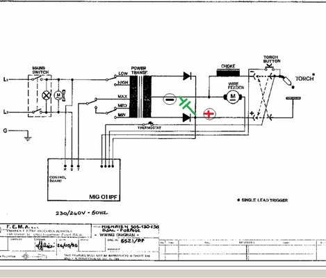
Peter Millerchip
New Member
- Messages
- 24
- Location
- Devon, U.K.
(My first post here and so apologies if this is the wrong section to post in. Perhaps the Mods could move it if its in the wrong place?)
This may take a bit to explain, but here goes :-
Background:-
Following some serious heart problems and several surgeries and having to sit on my bum for nearly two years recovering, I decided a new"challenge" might get me up and running again.
As a makee learnee model engineer, I have always thought it would be nice to be able to stick and wire weld, so as to be able to attempt better projects, plus crerate a bit of "sculpture" for my wife's garden.
I have just invested in a really cheapo Chinese gasless wire welder. Budget concerns meant finding the cheapest wire welder I could, and after a lot of trawling the net and reading many many posts, youtubes etc., came across this "Switzer" welder on E-bay (no connection/affiliation) as just about the cheapest at under £70.
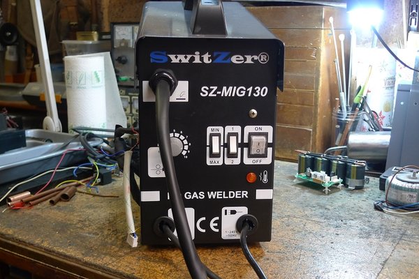
General view
It was marketed on E-Bay as an "inverter mig welder", which it clearly is not. However, the price was right.
(Just as an aside, I had words with the agents selling this on ebay, who had no idea what an "Inverter" was. Evidently they had relied on their suppliers' description (?from China?) who had possibly stretched the truth of the matter. Anyway, the sellers said they would immediately change their advert. description after we touched on "Trades Description Act" and so on. They were honestly unaware of what they were selling and of course offered to collect it and refund me.)
However, the price was right, so I kept it with a view to doing some mods to bring it up to a respectable DCEN machine.
Prior to my purchase, I had spent much time reading "stuff" on the Net about wire welding, and I must say that this site is by far the most useful, friendly and helpful I have found. Respectful chat is nice to find these days!
This welder - named a SwitZer SZ-MIG130 - manufactured in China by Zheijiang Juba Welding Equipments Manufacturing Cop. Ltd.
I suspect that the manufacturers make thousands of these in various forms and coloured boxes?
Anyway, a quick inspection of the (thin) "manual" reveals its a 240Volt input, 50-120Amp output at 37Volt max. Duty cycle is pathetic :- 105 @15%!!!
Flux cored wire dia :- 0.6 - 0.9mm.
Unfortunately, there is no circuit diagram or schematic.
Controls are two rocker switches which change taps on the primary side of the main transformer to give 4 "power settings" - between 30 and 37 Volt AC output as far as I can measure.
There is a wire feed motor speed controller knob - a 1 megohm log pot.
An overheat warning light and that's about it.
Internally there is a very good looking boat anchor of a mains transformer (the components and standard of assembly looks quite well done), a very small pcb which appears to be the wire motor controller, a thermal cut-out, and a very nice hefty muff fan at the back.
The wire feed motor is stamped 12V, 1A and under no load I measured 11v dc on its terminals.
There is also a label on the motor giving ?wire speeds? "2-11 /in" whatever that means?
The upper deck contains a standard (flat mounted) wire feed mechanism and wire spool axle.
The nozzle/trigger appears pretty heafty.
The clamp is somewhat flimsy!!
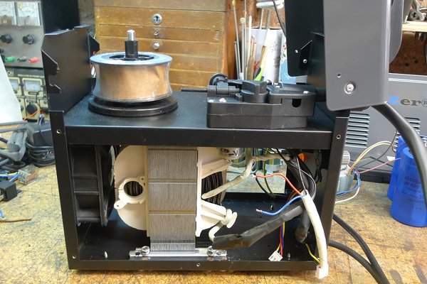
Note the transformer and very little else!
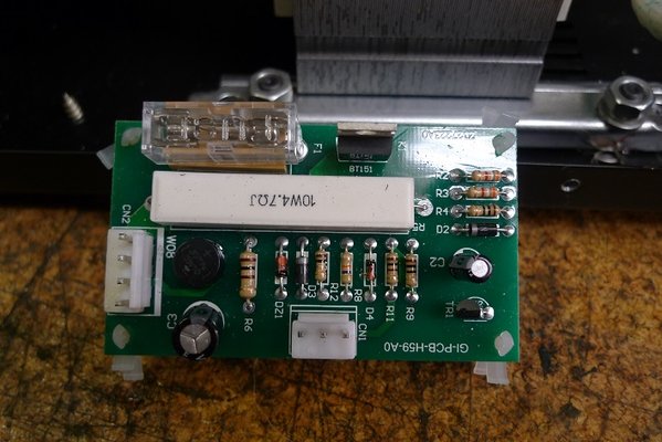
Circuit board - contains a tiny bridge rectifier, a couple of small electrolytics, a BT151 scr, a small switching transistor, a few resistors, signal diodes and small power diodes, etc. a fuse, and connectors to the pot (at the bottom) and the 4 way one (on the side) - two wires to the motor and a pair to the earth clamp and the trigger switch (the trigger is spring connected direct to the electrode tip thus providing 30-37volts AC).
I tried drawing a circuit diagram from the pcb layout but got horribly confused! I think this is some kind of pwm controller?
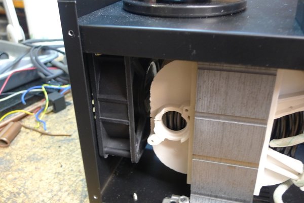
The muff fan - rated at 240V ac - runs off the mains switch.
That's the background explained.
The Project :- 1.simple mechanical stuff; 2. AC to DC conversion; 3. wire feed motor controller sort-out.
1. The first jobs done were to change the clamp for a decent Parweld heavy duty jobby.
Next, I removed the (chocolate) sheet metal screws which hold the transformer to a sub-frame and casing.
I re-drilled for M6 holes having shoved the tranny further back to get more space at the front, and used cap head bolts and nuts to secure. The fan still works fine.
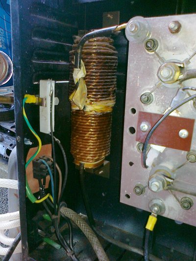
2. Next I intend to do the AC to DC conversion. At this stage I do not anticipate fitting a choke to the output line to the electrode.
On order is a three phase 1000 - 1600 Volt, 150 amp bridge rectifier (on a finned heat sink).
I have made up a reservoir "capacitor pack" viz:-
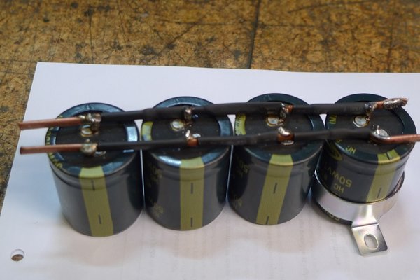
This is 4 X 15000uf 50V caps soldered to copper rods. This should fit in the base of the enclosure in front of the main Tranny.
Noted :- these caps do look rather small for their rated values?
I have a pair of 30,000uf big blue fat bellied screw terminal ones, but only rated at 40Volts which may be a bit close to the edge? They also take up a LOT of space.
I have yet to fit 10W power (bleed) resistors across them.
I do not foresee any problems putting this together, but my questions relate to the wire feed motor sort-out part of the project. (3)
Now here I am not sure how to proceed.
Once the DC conversion is done, I presume the voltage at the tip of the electrode (currently max. 37Volt AC) will be increased by ?up to 50%? because the AC out is being rectified and smoothed by the reservoir caps. So will I be looking at over 50Volts on the electrode?
Whatever this voltage is, it becomes the switched signal in the trigger wire.
I have the idea of removing the little motor control pcb completely.
To provide power for the basic wire feed motor, rather than fitting another tranny/rectifier etc., I could use a stabilised "wall wart" power supply? I have a 12Volt 1Amp one in mind.
It would mean simply drilling the front [panel for a mini power socket, and having to us a second mains socket for the wall wart itself.
I will use this power source to power a separate pwm motor controller (sourced via ebay, costs less than a tenner! - 12-48Volt, 40Amp motor controller module - in a nice case with control pot too!!) via the relay for the wire feed motor.
Relays seem to be a problem - they are either 24Volt, 12 volt (automotive) or 110/240Volt mains rated.
Because my trigger switch may be providing between 37 and (say) 50Volts, I need to step the output from the trigger switch down to 24Volts.
Again, on e-bay I have sourced a "Dc-DC Buck step-down 12-60Volt down to 3/6/9/12/24 volt out at 10Amps! (Just over a fiver).
So if I use this to attenuate the voltage signal on the trigger wire, I can then use it on a 24Volt relay?
Then, wire the relay contacts to power the motor and act as a motor brake to stop run-on.
Have I missed anything or made a total **** of it?
I would appreciate some help please.
Peter
This may take a bit to explain, but here goes :-
Background:-
Following some serious heart problems and several surgeries and having to sit on my bum for nearly two years recovering, I decided a new"challenge" might get me up and running again.
As a makee learnee model engineer, I have always thought it would be nice to be able to stick and wire weld, so as to be able to attempt better projects, plus crerate a bit of "sculpture" for my wife's garden.
I have just invested in a really cheapo Chinese gasless wire welder. Budget concerns meant finding the cheapest wire welder I could, and after a lot of trawling the net and reading many many posts, youtubes etc., came across this "Switzer" welder on E-bay (no connection/affiliation) as just about the cheapest at under £70.

General view
It was marketed on E-Bay as an "inverter mig welder", which it clearly is not. However, the price was right.
(Just as an aside, I had words with the agents selling this on ebay, who had no idea what an "Inverter" was. Evidently they had relied on their suppliers' description (?from China?) who had possibly stretched the truth of the matter. Anyway, the sellers said they would immediately change their advert. description after we touched on "Trades Description Act" and so on. They were honestly unaware of what they were selling and of course offered to collect it and refund me.)
However, the price was right, so I kept it with a view to doing some mods to bring it up to a respectable DCEN machine.
Prior to my purchase, I had spent much time reading "stuff" on the Net about wire welding, and I must say that this site is by far the most useful, friendly and helpful I have found. Respectful chat is nice to find these days!
This welder - named a SwitZer SZ-MIG130 - manufactured in China by Zheijiang Juba Welding Equipments Manufacturing Cop. Ltd.
I suspect that the manufacturers make thousands of these in various forms and coloured boxes?
Anyway, a quick inspection of the (thin) "manual" reveals its a 240Volt input, 50-120Amp output at 37Volt max. Duty cycle is pathetic :- 105 @15%!!!
Flux cored wire dia :- 0.6 - 0.9mm.
Unfortunately, there is no circuit diagram or schematic.
Controls are two rocker switches which change taps on the primary side of the main transformer to give 4 "power settings" - between 30 and 37 Volt AC output as far as I can measure.
There is a wire feed motor speed controller knob - a 1 megohm log pot.
An overheat warning light and that's about it.
Internally there is a very good looking boat anchor of a mains transformer (the components and standard of assembly looks quite well done), a very small pcb which appears to be the wire motor controller, a thermal cut-out, and a very nice hefty muff fan at the back.
The wire feed motor is stamped 12V, 1A and under no load I measured 11v dc on its terminals.
There is also a label on the motor giving ?wire speeds? "2-11 /in" whatever that means?
The upper deck contains a standard (flat mounted) wire feed mechanism and wire spool axle.
The nozzle/trigger appears pretty heafty.
The clamp is somewhat flimsy!!

Note the transformer and very little else!

Circuit board - contains a tiny bridge rectifier, a couple of small electrolytics, a BT151 scr, a small switching transistor, a few resistors, signal diodes and small power diodes, etc. a fuse, and connectors to the pot (at the bottom) and the 4 way one (on the side) - two wires to the motor and a pair to the earth clamp and the trigger switch (the trigger is spring connected direct to the electrode tip thus providing 30-37volts AC).
I tried drawing a circuit diagram from the pcb layout but got horribly confused! I think this is some kind of pwm controller?

The muff fan - rated at 240V ac - runs off the mains switch.
That's the background explained.
The Project :- 1.simple mechanical stuff; 2. AC to DC conversion; 3. wire feed motor controller sort-out.
1. The first jobs done were to change the clamp for a decent Parweld heavy duty jobby.
Next, I removed the (chocolate) sheet metal screws which hold the transformer to a sub-frame and casing.
I re-drilled for M6 holes having shoved the tranny further back to get more space at the front, and used cap head bolts and nuts to secure. The fan still works fine.
2. Next I intend to do the AC to DC conversion. At this stage I do not anticipate fitting a choke to the output line to the electrode.
On order is a three phase 1000 - 1600 Volt, 150 amp bridge rectifier (on a finned heat sink).
I have made up a reservoir "capacitor pack" viz:-

This is 4 X 15000uf 50V caps soldered to copper rods. This should fit in the base of the enclosure in front of the main Tranny.
Noted :- these caps do look rather small for their rated values?
I have a pair of 30,000uf big blue fat bellied screw terminal ones, but only rated at 40Volts which may be a bit close to the edge? They also take up a LOT of space.
I have yet to fit 10W power (bleed) resistors across them.
I do not foresee any problems putting this together, but my questions relate to the wire feed motor sort-out part of the project. (3)
Now here I am not sure how to proceed.
Once the DC conversion is done, I presume the voltage at the tip of the electrode (currently max. 37Volt AC) will be increased by ?up to 50%? because the AC out is being rectified and smoothed by the reservoir caps. So will I be looking at over 50Volts on the electrode?
Whatever this voltage is, it becomes the switched signal in the trigger wire.
I have the idea of removing the little motor control pcb completely.
To provide power for the basic wire feed motor, rather than fitting another tranny/rectifier etc., I could use a stabilised "wall wart" power supply? I have a 12Volt 1Amp one in mind.
It would mean simply drilling the front [panel for a mini power socket, and having to us a second mains socket for the wall wart itself.
I will use this power source to power a separate pwm motor controller (sourced via ebay, costs less than a tenner! - 12-48Volt, 40Amp motor controller module - in a nice case with control pot too!!) via the relay for the wire feed motor.
Relays seem to be a problem - they are either 24Volt, 12 volt (automotive) or 110/240Volt mains rated.
Because my trigger switch may be providing between 37 and (say) 50Volts, I need to step the output from the trigger switch down to 24Volts.
Again, on e-bay I have sourced a "Dc-DC Buck step-down 12-60Volt down to 3/6/9/12/24 volt out at 10Amps! (Just over a fiver).
So if I use this to attenuate the voltage signal on the trigger wire, I can then use it on a 24Volt relay?
Then, wire the relay contacts to power the motor and act as a motor brake to stop run-on.
Have I missed anything or made a total **** of it?
I would appreciate some help please.
Peter


 ) transformer mounted on the pcb for the supply needed before/connected to the primary side
