You are using an out of date browser. It may not display this or other websites correctly.
You should upgrade or use an alternative browser.
You should upgrade or use an alternative browser.
Senior project
- Thread starter Chippie
- Start date
Chippie
Member
- Messages
- 855
- Location
- Newcastle upon Tyne, UK
Ok, a bit more work done on the engine…
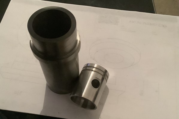
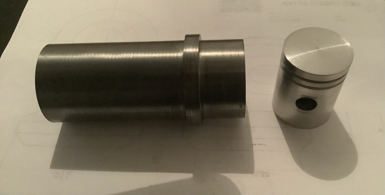
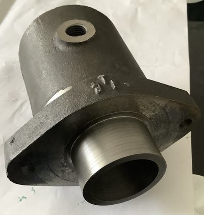
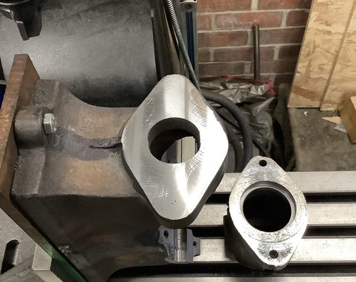
The cylinder, bored to 38mm, actual size is 37.8 allowing for honing and lapping….the outer dia. is 48mm, the larger diameter is 54, locates in the cylinder and is sealed with an O ring for the water jacket. There’s a gasket at the opposite end…meeting the cylinder head …..eventually…
Boring was a challenge, the overall length being 115.45mm….had to make a ‘special boring bar’ from a length of 3/4” bms round….
Cast iron is messy smelly stuff! I hate it!
More to come, stay tuned..


not done it yet
Member
- Messages
- 2,542
- Location
- Lincs/cambs/Rutland/Northants
Only just seen this thread. Looking good. I would have thought bronze, not phosphor-bronze for the small end - but presumably that was supplied with the kit? Handy to have the gears already cut, not starting with blanks.
The other thing that surprises me is the supplied rings, making the piston and bore a closely defined measurement. I would prefer to have simply made the piston and bore to fit and made the rings to suit the finished diameter, whatever it finished at. Presumably you made a boring bar for between-centres boring, to make the cylinder bore?
Keep up the good work.
Is it really O/A length of 8”? Or does O/A stand for something else?
What machines are you using? I shall be watching progress with interest. I may start to make a model engine - but likely never get it finished, so not rushing into a decision.
Chippie
Member
- Messages
- 855
- Location
- Newcastle upon Tyne, UK
Ok, ventured out into the cold….
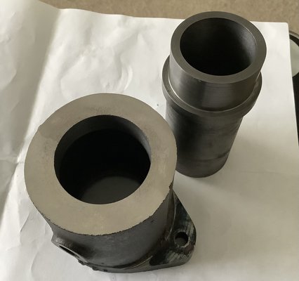
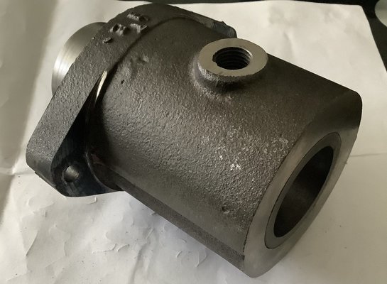
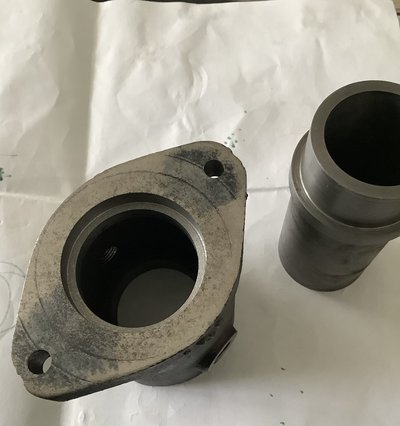
Some work done on the cylinder jacket this time. Quite a challenge as the finished length is 90mm and requires boring through to a finished size of 48mm, which is the o/d of the cylinder liner.
Then the flanged end needs a recess machining to accept the liner shoulder, at 54mm.
Anyway some pictures to look at…..


Chippie
Member
- Messages
- 855
- Location
- Newcastle upon Tyne, UK
Well after a bit of an absence, what with Christmas and all….
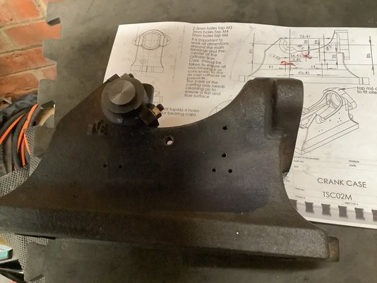
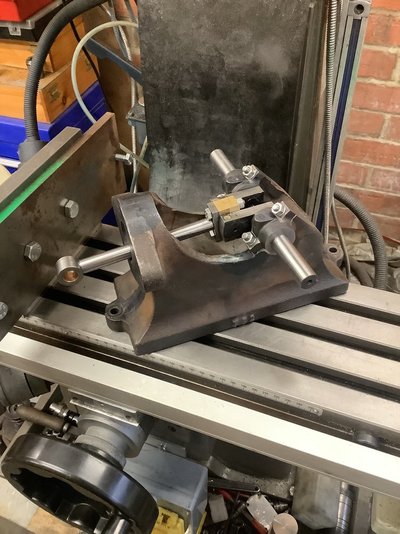
Further progress, I managed to drill and ream the bearing supports and caps, (if you want to call it that…) without any major dramas..
The main thing is to ensure that the bearing support is relatively true to the base, and the supports are true to each other so that the crank is at 90 degrees to the axis of the cylinder and piston…Hence the ‘cobbled together, mounting plate with angle plate on the mill table…
More to follow, flywheels next or cylinder mounting face?
Stay tuned…


Chippie
Member
- Messages
- 855
- Location
- Newcastle upon Tyne, UK
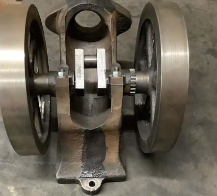
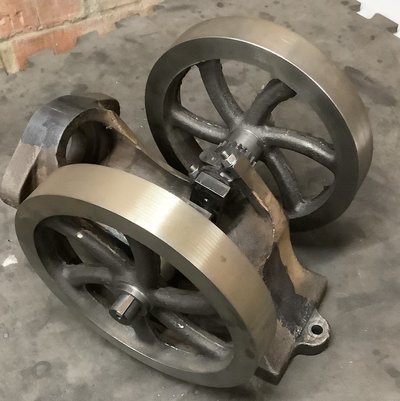
Progress so far,
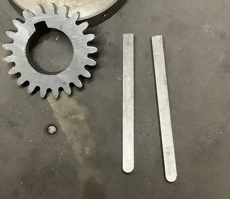
The crank timing gear has its key way broached and keys cut to length (approx..)
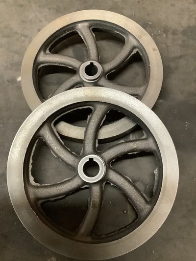
The flywheels now have keyways broached too…
Broaching was done in the lathe, flywheel held in the chuck, then the broaching tool made up from a 1/2” boring tool with some 4mm hss held in as the ‘cutting tool’….I couldn’t justify spend ££££’s on a set of broaches that would be used once in a blue moon….
Satisfied? Absolutely, jobs a good ‘un….
All assembled and turns over fine….
More to follow.


Chippie
Member
- Messages
- 855
- Location
- Newcastle upon Tyne, UK
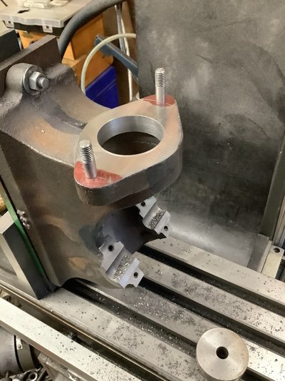
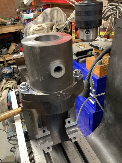
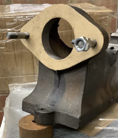
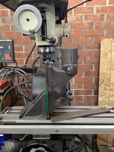
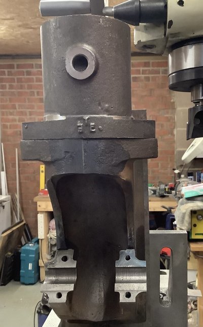
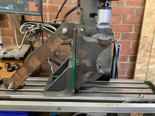
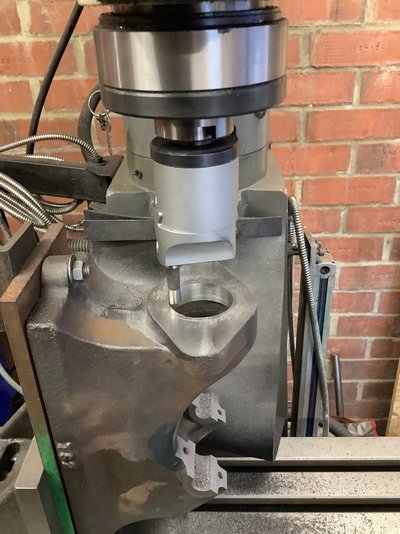
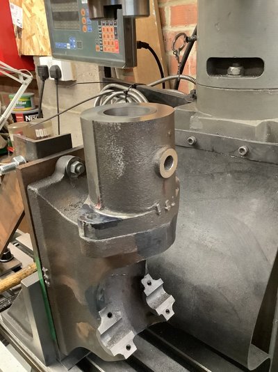
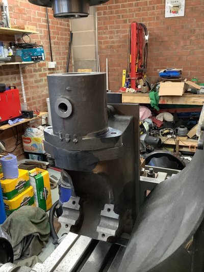
Today, on with the main casting.
The mating face for the cylinder requires facing as it’s not flat enough for the cylinder to bolt to, although there is a gasket (joint?) in between them.
So a few thou machine off with a face mill and its done!
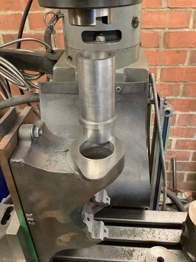
While the casting is setup like this, I‘ll bore the hole to accept the spigot on the cylinder liner, before drilling/tapping the holes for the cylinder bolts.
This ensures the whole assembly looks ‘right’…when bolted up. ( I hope ! )


Chippie
Member
- Messages
- 855
- Location
- Newcastle upon Tyne, UK
So, during the course of all of this work, some may wonder how do you achieve the accuracy required to build something like this?
I know some of the more ‘seasoned’ machinists among us won’t condone what I‘ve done along the way but it’s a case of what works for you….
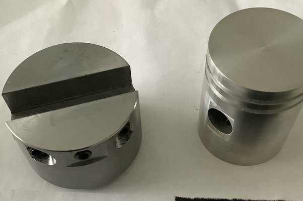
Some of the parts require a degree of accuracy, such as the cylinder bore, the liner’s outside dimension and it’s internal bore and the piston. Rather than shooting for an exact dimension, although there are tolerances on some measurements, I’ve gone for the ‘fit‘ approach although care has been taken in achieving the desired sizes.
One of the items that does require an accurate size is the main body casting, as many of the items that are attached to it are referenced from the crank housing and the cylinder face.
I guess the setup shown for the main casting above doesn’t reflect the care needed, but let’s not forget, this isnt about building a high speed jet engine more of an agricultural piece of machinery…and built from castings!
We shall see how it turns out on completion, but there’s still a way to go yet…
Criticism welcome…
Chippie
Member
- Messages
- 855
- Location
- Newcastle upon Tyne, UK
Morrisman
Member
- Messages
- 8,106
- Location
- Staffordshire, England
Working out how to hold components to machine them is always an interesting challenge. Back in the day I used to machine castings and components for some Swiss guy who was into classic and vintage car racing.
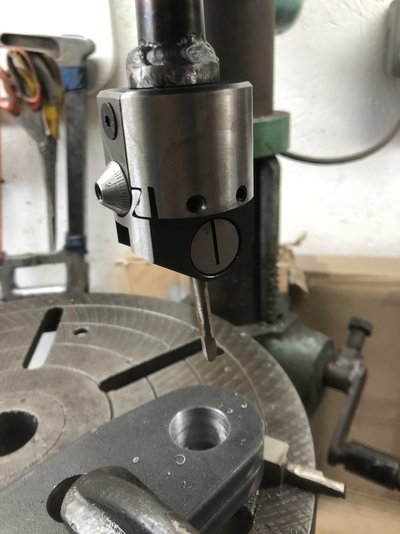
I did some successful boring in my cheapie home drill press a few days ago, not quite in your league though.
Where there’s a will, there’s a way.
I did some successful boring in my cheapie home drill press a few days ago, not quite in your league though.
Where there’s a will, there’s a way.


Chippie
Member
- Messages
- 855
- Location
- Newcastle upon Tyne, UK
And to answer the previous post on sourcing parts, they all came as an unmachined kit from The Engineers Emporium.
The kit comprises the main body casting, cast cylinder, cast cylinder head, 2 cast flywheels, gears and rings and miscellaneous parts.
Theres a selection of other loose material to fabricate/machine the piston, conrod
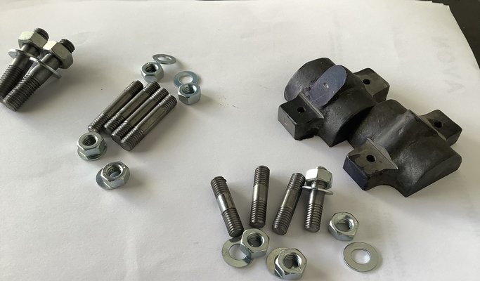
The constructor needs to provide other material not provided to make the valves, gudgeon pin, studs nuts and washers….
I wouldn’t say it was a beginners kit by any stretch, I’m not a machinist, just someone like John Doubleboost ( I ain’t a mechanic either ) that ****** about…
Comments welcome.
slim_boy_fat
Forum Supporter
- Messages
- 29,540
- Location
- Scottish Highlands
redlig
Member
- Messages
- 3,612
- Location
- wiltshire uk
No. do a Burke and Hare lot less digging or answering questions.The morgue?
View attachment 435966
Chippie
Member
- Messages
- 855
- Location
- Newcastle upon Tyne, UK


 (sorry)
