You are using an out of date browser. It may not display this or other websites correctly.
You should upgrade or use an alternative browser.
You should upgrade or use an alternative browser.
berlan bmig140 arcing without trigger being pulled
- Thread starter croagy
- Start date
Reviving my own thread here
It's died again but this time when you pull the trigger there is no wire feed but will still arc.
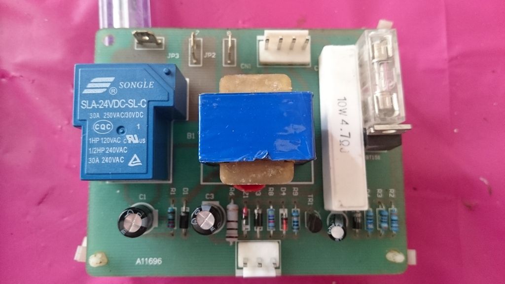
In the pic of the board what is the the right bang in the middle beside the relay? Looking at it the there's insulation around the coiled copper wire inside and looks a little melted.. Could this cause the problem or what does that do?
I heard a pop when it died no smoke tho
Thanks
Craig
the snooper
getting older by the day
- Messages
- 21,063
- Location
- Hull UK
that is the auxiliary transformer that supplies power to the pcb, you need to test its output voltage
mike 109444
Member
- Messages
- 4,839
Make sure you disconnect the motor BEFORE apply external power to the motor or you will feed voltage into the pcb and could screw it up!
As Snooper has said that is a transformer and should have AC voltage into one side and a lower AC out. probable 240AC in one side and 12 to 24AC out.
Input will probable be one of the two black circles pairs and out on the other pair. Remember to set your meter to AC.
Also if something went "pop" have you checked the fuse on the pcb !!
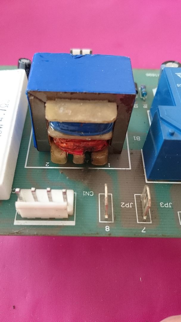
Would anyone know the spec of the transformer? It has some scorching around it
http://m.rapidonline.com/Catalogue/...=2&followSearch=9925&keywords=transformer+12v
http://m.rapidonline.com/Catalogue/...=2&followSearch=9925&keywords=transformer+12v
skotl
Forum Supporter
- Messages
- 10,394
- Location
- Edinburgh, UK
The two pins will be the AC in. A transformer with two output pins is a single winding with a single voltage output, and a 4 pin will be two windings (for example, 50-0V and 50-0V)
A 3 pin output is likely also two windings but the middle pin is shared (50-0-50, or 100V across the outer pins).
So the good news is that a transformer with 4 output pins / 2 windings will be easy to retrofit to your board (although you may need to mount it off the board and attach it with cables).
The not so good news is that I don't know what output voltage your PCB will expect - Mike's the man for that!
At least it sounds like a cheap fix

the snooper
getting older by the day
- Messages
- 21,063
- Location
- Hull UK
Depends which side has gone it could be wear and tear or if secondary it could be shorted rectifierAny ideas what might cause it to blow?
mike 109444
Member
- Messages
- 4,839
I would have thought it would be a 24vAC out and the extra pins may not even be used and are there from manufacture and allow the people winding the transformer to select which pins thy use when winding it. The extra pins also allow for better support when pcb mounting.
If you look at these pcbs from Clarke machines you will see that several pins are not even soldered to the board and some connect to the same part of the track as again they are not connected to the winding's
Just getting a 240AC in to 24AC out that is physically bigger should suffice and mount it near the pcb and run wires to pcb. Insulate the wires as some will be carrying 240v.
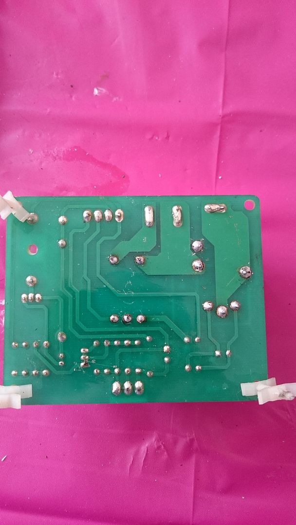
Do you have a pic of the under side of pcb ?
I'll take the transformer off the board and get some pics up of both showing where it blew and how it's attached to the board.. It has all 5 pins soldered to the board in dedicate holes.. There are no spare pins in the transformer
Thanks for the replies.
Thanks for the replies.
mike 109444
Member
- Messages
- 4,839
No I don't think that is what you need. You need a SINGLE out put. If you look at the attached image you will see that the middle pin is soldered to the pcb BUT it is not used (there is no track to it!)
With those small pcb type transformers they have a very thing wire on one of the input wires (hidden under the plastic tape) that is the fuse for the transformer, very crude!! It fails if the transformer is over loaded.
As you have the transformer remover then with all the plugs removed from pcb, meter between the X and Z solder pads on pcb with meter set to lowest Ohms setting. you may find you get a short (meter reading 00.00) indicating something on pcb is short. Report back if that is so. Also where does pin W's wire on the 4 pin plug go to ?
mike 109444
Member
- Messages
- 4,839


