You are using an out of date browser. It may not display this or other websites correctly.
You should upgrade or use an alternative browser.
You should upgrade or use an alternative browser.
berlan bmig140 arcing without trigger being pulled
- Thread starter croagy
- Start date
mike 109444
Member
- Messages
- 4,747
Q1 Did you check the resistance across the X an Z for a short ?Bump
Q2 Did you get and fit a new transformer ?
mike 109444
Member
- Messages
- 4,747
Is it possible that you fitted the new transformer the wrong way round ?
How much resistance did you find when you metered across x and z ?
How much resistance did you find when you metered across x and z ?
the snooper
getting older by the day
- Messages
- 21,063
- Location
- Hull UK
My thoughts exactly when I read itIs it possible that you fitted the new transformer the wrong way round ?
How much resistance did you find when you metered across x and z ?
mike 109444
Member
- Messages
- 4,747
It could be you have a "short circuit" on the secondary side of the transformer as in across X and Z. You said you got a resistance reading across there, what was the reading ? Try unplugging the 4 pin plug and note the reading then, is it different ?
Does the wire feed control connect to the 3 pin plug at bottom of pcb ?
If the W pin connects to the motor where does the second wire from/to the motor go ? (back onto the pcb 4 pin plug?)
Also note the small transistor at the bottom looks to have a blob across the bottom two pins ??
Does the wire feed control connect to the 3 pin plug at bottom of pcb ?
If the W pin connects to the motor where does the second wire from/to the motor go ? (back onto the pcb 4 pin plug?)
Also note the small transistor at the bottom looks to have a blob across the bottom two pins ??
the snooper
getting older by the day
- Messages
- 21,063
- Location
- Hull UK
de solder the transformer (make sure you are safe) power it up and measure for a voltage on the output side of the transformer there should be no voltage but the only way it can go bang is if you put mains into the secondary windings of the transformer
linuxmadeira
New Member
- Messages
- 13
- Location
- Funchal - Potugal
Can you help me
I have my machine Berlan bmig 140
I disassembled my machine, to paint, because it had metal rust, lost the wire connections, no spark and not even advance the wire :-(
I need a scheme, or complete photos, I really need bmig 140 to work
I already did fuse test, it gave ok and others, there are no burned parts
thank you very much
linuxmadeira
New Member
- Messages
- 13
- Location
- Funchal - Potugal
I already tested all the parts, relay, diode, torch, motor launch wire (12V), button, everything is ok,
When I turn on the welding machine, only one piece fan is working, rest is all stopped ???
PCB board receives 240v and goes to 24v
I tested with multimeter, all wires, not broken, everything is ok
There is anything is hidden, I am not seeing the source of the problem !!!
When I turn on the welding machine, only one piece fan is working, rest is all stopped ???
PCB board receives 240v and goes to 24v
I tested with multimeter, all wires, not broken, everything is ok
There is anything is hidden, I am not seeing the source of the problem !!!
linuxmadeira
New Member
- Messages
- 13
- Location
- Funchal - Potugal
I could do a direct test, with the machine turned on, connect relay (PCB) with 12v battery with correct polarity, to see if it gives some current voltage signal,
but I do not want to do the dangerous experiment, can give very big problems!
but I do not want to do the dangerous experiment, can give very big problems!
linuxmadeira
New Member
- Messages
- 13
- Location
- Funchal - Potugal
sorry i write bad english i am portuguese But you understand I'm trying to convey my machine problem
A search for Berlan BMIG 140 does produce a few results, with some internal pictures that may help you to confirm that you put all the wires back in the correct places. For example, this Czech site:
http://www.svarforum.cz/forum/viewtopic.php?id=11511
On the PCB, you have 24v - is that AC only, or is there a rectifier, and have you also checked the 24v DC ?
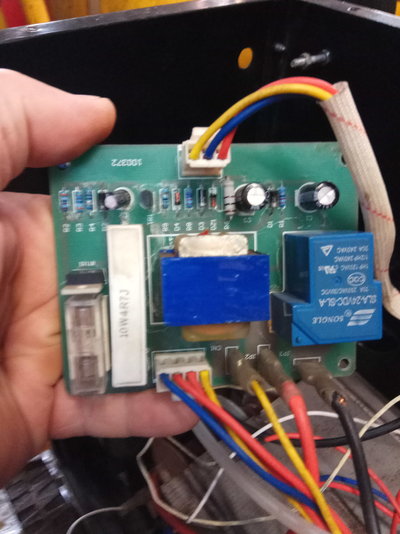
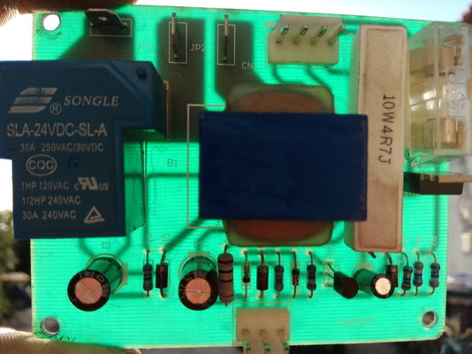
The T-shaped blue object is the relay which should be enabling power for the primary of the main welding transformer. If you can identify the relay coil connections, there should be about 100 to 200 Ohms resistance there. The relay contacts will probably have wider printed tracks and will go to external wires that feed 240v AC mains to the main transformer.
You could put your voltmeter across the relay coil and, carefully with the machine powered up, check that voltage is applied to the coil when the torch trigger is pressed.
And welcome to the Forum ! Do you run Linux ? ( I'm on Ubuntu 14.04 )
linuxmadeira
New Member
- Messages
- 13
- Location
- Funchal - Potugal
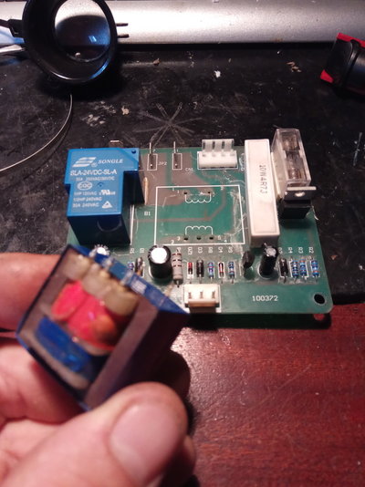
my berlan bmig 140 - PCB
-
 IMG_20191002_183559.jpg269.5 KB · Views: 167
 -
 IMG_20191002_190901.jpg199.5 KB · Views: 147
 -
 IMG_20191002_190937.jpg282.1 KB · Views: 130
 -
 IMG_20191002_190953.jpg217.9 KB · Views: 155
 -
 IMG_20191002_191043.jpg374.6 KB · Views: 147
 -
 IMG_20191002_191126.jpg235.5 KB · Views: 143
 -
 IMG_20191002_191137.jpg220.8 KB · Views: 188
 -
 IMG_20191002_183542.jpg235.6 KB · Views: 174
linuxmadeira
New Member
- Messages
- 13
- Location
- Funchal - Potugal
linuxmadeira
New Member
- Messages
- 13
- Location
- Funchal - Potugal
I found the problem
linuxmadeira
New Member
- Messages
- 13
- Location
- Funchal - Potugal
correct connection
linuxmadeira
New Member
- Messages
- 13
- Location
- Funchal - Potugal
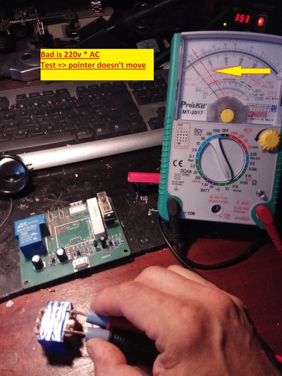
multimeter test
linuxmadeira
New Member
- Messages
- 13
- Location
- Funchal - Potugal
test lamp 24v


