You are using an out of date browser. It may not display this or other websites correctly.
You should upgrade or use an alternative browser.
You should upgrade or use an alternative browser.
NBC Auto Weld 2 - inside a 50 year old MIG
- Thread starter a111r
- Start date
Post #12 of this thread:that parchment-like schematic recently and it was helpful to a degree. For reasons unknown, it's not showing in the threads now.
NBC Autoweld2 control transformer burned out, can anyone help?
I have an NBC (Butters) AutoWeld2 which is God knows how old (or it may be older than God, I'm not sure). Anyway, the control transformer (wot makes things click) has burned out - the main transformers are still fine. I reckon it should be easy enough to pop a new universal transformer in...
www.mig-welding.co.uk
No progress has been made without 110 vdc.Did you get the motor working or is it still the show stopper ?
It should run on much less than that. I've ran brushed 240V AC motors on 12V DC for test purposes. Another alternative is to crank your mig up to maximum volts output, release the wire feed or remove the wire, connect the 110V motor to the torch and earth clamp and press the trigger. You'll get 1/3 of the voltage to the motor and that should be more than enough to spin it up.No progress has been made without 110 vdc.
I did this test tonight and the motor is fine.It should run on much less than that. I've ran brushed 240V AC motors on 12V DC for test purposes. Another alternative is to crank your mig up to maximum volts output, release the wire feed or remove the wire, connect the 110V motor to the torch and earth clamp and press the trigger. You'll get 1/3 of the voltage to the motor and that should be more than enough to spin it up.
Getting there.
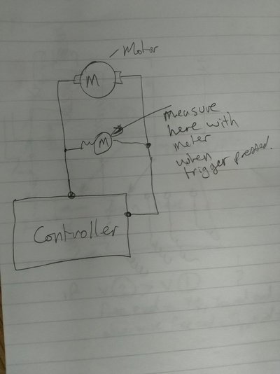
Does the motor get any voltage when the torch trigger is pressed ? Try measuring the voltage across the motor directly, don't measure it from one wire to ground or other terminal, measure it directly across the motor. You could quite feasibly get 110V measuring either wire to 0V/ground but the motor won't run because there is no current path back to ground.
No, put it all together, bolt it back into the chassis - it obviously works because you had it going roundThanks DSR. Are you saying measure the voltage across the field coil and armature?
 . Connect it back up and then measure the voltage across the terminals that you connect it to. I'm assuming that it's a standard DC brushed motor with only two terminals on it. Just want to find out if when the trigger is pressed, you get 110V across it or 0V.
It is a 4-terminal motor. The first thread that I linked to in post #60 describes the motor as shunt-wound. I think it could be better described as a separately-excited ( sepex ) motor, with speed control by varying the armature current.
( Same as my 2001 Citroen Berlingo Electrique van.)
( Same as my 2001 Citroen Berlingo Electrique van.)
The first thread that I linked to in post #60 describes the motor as shunt-wound. I think it could be better described as a separately-excited ( sepex ) motor, with speed control by varying the armature current.
That's different then

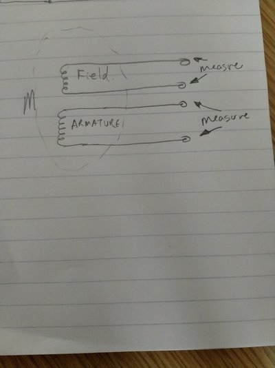
How many wires are there going to the motor ? I would expect a minimum of three and the diagram @eddie49 linked to shows four wires. Assuming that yours is the same as the diagram, with four wires, identify the field and armature wires and measure the voltage across the field then do the same for the armature ala :-

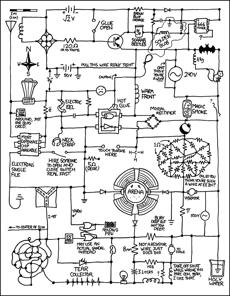
I think the circuit is wrong BTW - I have found a more up to date version :-

(Apologies to xkcd.com).
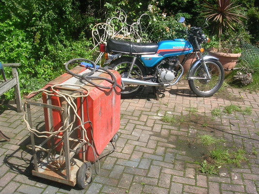
That bike is in better condition than most of us hahahahaExcellent idea, thanks! I'll wire up the field and armature in parallel and try that.
I've been distracted by another 1970s acquisition over the past few days (not the French chairs).
View attachment 298994
If you don't get a voltage on both readings then more investigation is needed. I can't see anything on the circuit or the photos you have supplied that looks remotely like an electronic speed controller. When it was made, power transistors and thyristors etc. were still relatively new and having something to control a 100V motor would have been expensive. I think the motor speed is controlled directly using the speed control potentiometer, it's probably a wire wound high power job so have a look at that at well as checking the voltage.Yes, it's four wires to the field and armature of the shunt wound motor.
I'll try that, thanks. Although I think I've tried that before.
The missing relay is next to try but I need to convert it to DC first...
I'd also look to make sure the wire feed transformer is giving out 110V AC and trace the 110V through the wire size switch to the pot and then to the motor. Be careful with the wire feed transformer - I think it may be an auto transformer so have mains voltage across the two outer pins and use a centre tap to provide the 110V. Not quite sure what the wire size switch does - it's not too clear on the circuit diagram but when you are measuring the voltages, make sure you measure them with the switch in both positions as well.
It actually looks very simple and there are no mysterious electronics in the way, a good old fashioned rheostat in series with the field coil or the armature will work very well if it can handle the current.
Indeed it is, mate. Pop over and have a look if you like?That bike is in better condition than most of us hahahaha
It's had a recent "£300 service by local experts", which will no doubt explain the overly stiff clutch and poor idle, after a points change.
If you don't get a voltage on both readings then more investigation is needed. I can't see anything on the circuit or the photos you have supplied that looks remotely like an electronic speed controller. When it was made, power transistors and thyristors etc. were still relatively new and having something to control a 100V motor would have been expensive. I think the motor speed is controlled directly using the speed control potentiometer, it's probably a wire wound high power job so have a look at that at well as checking the voltage.
I'd also look to make sure the wire feed transformer is giving out 110V AC and trace the 110V through the wire size switch to the pot and then to the motor. Be careful with the wire feed transformer - I think it may be an auto transformer so have mains voltage across the two outer pins and use a centre tap to provide the 110V. Not quite sure what the wire size switch does - it's not too clear on the circuit diagram but when you are measuring the voltages, make sure you measure them with the switch in both positions as well.
It actually looks very simple and there are no mysterious electronics in the way, a good old fashioned rheostat in series with the field coil or the armature will work very well if it can handle the current.
Thanks again DSR.
I mentioned earlier in the thread that the wire speed pot / or wire wound rheostat looked dodgy and was maybe not OEM, having just 90 degrees of sweep, compared to the knob's near 360 degree range.
I tested it and the resistance variation seemed 'OK'. Are we on ten pages yet....?

ranchero
Member
- Messages
- 211
- Location
- southampton
i had to replace mine cos it broke up. found one on the intertwit sorry cant remember who from. UK company a bit spendy but very well made fit same as old one and works well so i am happy. well post name of company if i can find the receiptThanks again DSR.
I mentioned earlier in the thread that the wire speed pot / or wire wound rheostat looked dodgy and was maybe not OEM, having just 90 degrees of sweep, compared to the knob's near 360 degree range.
That's definitely a bastard size if it isn't broken. Apart from multi-turn pots, I've never seen one that isn't 270 degrees angle of rotation. It's something to definitely check. That it's 90 degrees and not 270 would say that the track has broken and is jamming full rotation. Can you get a close up photo of the pot, just to confirm which one it is, it looks like it's the very bottom one which doesn't look very healthy at all.Thanks again DSR.
I mentioned earlier in the thread that the wire speed pot / or wire wound rheostat looked dodgy and was maybe not OEM, having just 90 degrees of sweep, compared to the knob's near 360 degree range.
I tested it and the resistance variation seemed 'OK'. Are we on ten pages yet....?
Also measure the voltage across and to the pot and swing the pot end to end and see if the voltage changes. If you do get a voltage to the pot, short both of the wires out and then press the trigger and see if the motor runs at full speed.


