BChild
SIP - enough with the mods!!!!
- Messages
- 1,023
Can you post the modified circuit as I cant see that this will work?
GTG did the diagram below earlier in the thread - I hope that helps
Can you post the modified circuit as I cant see that this will work?
You just have 87 and 87a swapped.


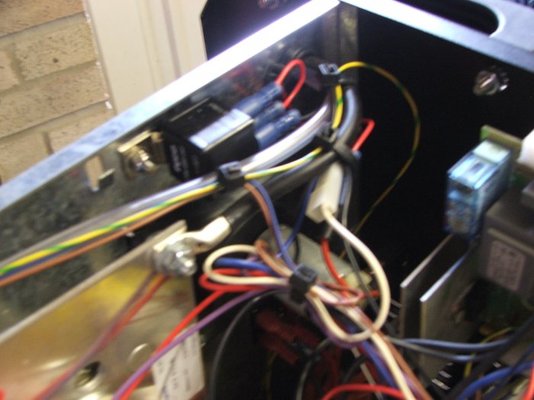
Choices are - fit multi turn 100K or 1000K pot or nail varnish the current one in a fixed position so it's unaffected by movement
I think the nail varnish option is worth a crack - quick and easy and if it doesn't work I'll replace the pot
PS it still has "play" in the wire between the wire feed roller and the end of the torch - It's about 5mm or movement - I've changed the tip for a new one and checked out the wire feed motor (no play there) so I am putting this down to the eurotorch and metal liner offering little or no resistance to wire feed and a curve in the torch lead in normal use - I'll see if I still have play when the torch is extended straight out unless anyone else thinks it's normal

You need to replace it with a 100 Ohm trim-pot. The 1K Ohm is too high a resistance and the range of adjustment is right up against the lower end. Later SIPs use 100 Ohm. I replaced mine and it made a huge difference - the range of adjustment is much wider and more central. I wouldn't say there is any need to use a multi-turn pot for this but I can't think that it would do any harm.What is now annoying me is the welder settings change every time you move it - I know what the problem is so should be easily fixed - that 1000 ohm trim pot moves whenever the welder gets bumped and this is changing my base start point so writing settings down for future reference is a waste of time.
Glad you got it sussed. The braking really is impressive, isn't it?
You need to replace it with a 100 Ohm trim-pot. The 1K Ohm is too high a resistance and the range of adjustment is right up against the lower end. Later SIPs use 100 Ohm. I replaced mine and it made a huge difference - the range of adjustment is much wider and more central. I wouldn't say there is any need to use a multi-turn pot for this but I can't think that it would do any harm.


I you decide to do something more elaborate , with your braking circuit.
http://books.google.com/books?id=99...ndD7CA&sa=X&oi=book_result&ct=result&resnum=7
The relay brake has been tried on mine. That's why I mentioned itI'll be interested to see what he makes of this bstardised SIP it as things like the ten turn pot and counter, and relay brake haven't been tried on one here (not that I can find)
The relay brake has been tried on mine. That's why I mentioned it
Regarding R Kraft's link, more sophisticated will probably give better results up to a point but the SIP wire-feed motor is so weedy that I can't imagine its inertia and that of the feed mechanism represents much of a strain. A resistor along with the relay would probably be the most complex solution for this that I would consider worthwhile for a SIP.
Yes, that would be feasible. It would just take some working out (or measurement) to decide the power rating of the pot so as not to damage it on maximum braking from maximum speed.I was thinking more along the lines of using a pot in place of R1, to allow adjustment of the coasting cycle.
BChild had mentioned using a pot directly in the braking circuit.
Yes, that would be feasible. It would just take some working out (or measurement) to decide the power rating of the pot so as not to damage it on maximum braking from maximum speed.


 Would be interested to know why the Clarke seems better with the same/similar motor.


