You are using an out of date browser. It may not display this or other websites correctly.
You should upgrade or use an alternative browser.
You should upgrade or use an alternative browser.
Stuff you have made today
- Thread starter God mode restorations
- Start date
doubleboost
Member
- Messages
- 3,830
- Location
- Newcastle upon Tyne England
brightspark
Member
- Messages
- 40,554
- Location
- yarm stockton on tees
don't be .had them 3 days in a row
 very nice but only once a week
doubleboost
Member
- Messages
- 3,830
- Location
- Newcastle upon Tyne England
3 times once a week loldon't be .had them 3 days in a rowvery nice but only once a week

Nauticus
If l let my mind wander, its often gone for weeks!
- Messages
- 86
- Location
- Lincolnshire, UK.
I built my work/welding table a few months ago. It is 2m long by 1m wide. The frame is all 50mm x 3mm hollow section with 50mm hollow 'cross slats' at approx 30mm intervals.
The top is 'framed' with the 50mm hollow all the way round the edge, and it is covered by a single 2m x 1m steel sheet 4mm thick (about the maximum weight I could handle on my own without resorting to mechanically assisted maneuvering).
I plan to mag drill, tap and use countersunk machine screws to secure the sheet to the frame. (But for the moment it;s just held in place by two or three tack welds at just one corner - plus it's weight - 62.8kg).
Being a 'multi purpose; bench, there are tines when I need a vice - and there are times where a vice could get in the way. Also, I didn't really want to start drilling holes in the bench only to find I need to change location and leave vacant holes.
I decided to build a vice holder that I could clamp to almost any part of the table surround, and quickly remove when not needed.
I had some short left-over sections of 50mm x 3mm angle, and also some 50mm x 3mm flat.
The 3mm thick angle was doubled up to give 6mm thick jaws. The 50mm flat was used both as a side stiffener and also to fill in the top plate. With a couple of hefty nuts welded to the jaws and I had a very strong and secure mount for a vice.
I think the nuts and bolts were for a tow ball hitch.
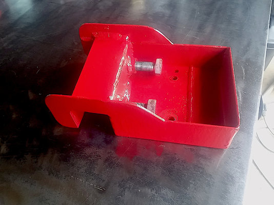
The above image shows the mount upside down. The clamping bolts can be clearly seen.
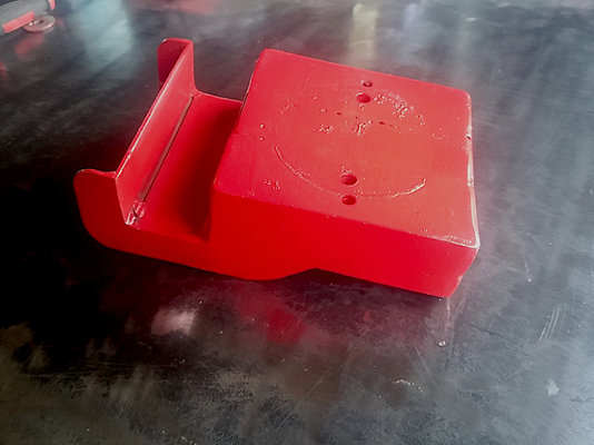
The above image shows the mount the right way up. Two lots of holes are for two different vices - I had a small swivel vice on first, then found a fixed vice.
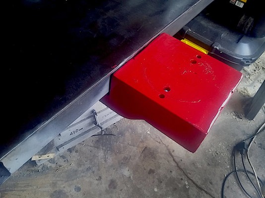
Here it is clamped to the bench. There is no perceptible flexing or distortion when tightening the clamp bolts. Its already been on and off the bench several times and is still a tight fit to lift it into place.
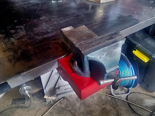
And now (above) with a smallish fixed vice bolted in place.
Surprisingly, it is absolutely solid with no movement or flexing. It has now been well tested by pulling and hammering bends into 50mm flat in the vice jaws, and then hammering the bends out of said 50mm flat on the 'anvil' plate.
Reaching underneath with a ring spanner can quickly slacken the two bolts to either remove the vice completely, or mount it to another section of the table.
This afternoon it got its final coat of paint.
Malc.
The top is 'framed' with the 50mm hollow all the way round the edge, and it is covered by a single 2m x 1m steel sheet 4mm thick (about the maximum weight I could handle on my own without resorting to mechanically assisted maneuvering).
I plan to mag drill, tap and use countersunk machine screws to secure the sheet to the frame. (But for the moment it;s just held in place by two or three tack welds at just one corner - plus it's weight - 62.8kg).
Being a 'multi purpose; bench, there are tines when I need a vice - and there are times where a vice could get in the way. Also, I didn't really want to start drilling holes in the bench only to find I need to change location and leave vacant holes.
I decided to build a vice holder that I could clamp to almost any part of the table surround, and quickly remove when not needed.
I had some short left-over sections of 50mm x 3mm angle, and also some 50mm x 3mm flat.
The 3mm thick angle was doubled up to give 6mm thick jaws. The 50mm flat was used both as a side stiffener and also to fill in the top plate. With a couple of hefty nuts welded to the jaws and I had a very strong and secure mount for a vice.
I think the nuts and bolts were for a tow ball hitch.

The above image shows the mount upside down. The clamping bolts can be clearly seen.

The above image shows the mount the right way up. Two lots of holes are for two different vices - I had a small swivel vice on first, then found a fixed vice.

Here it is clamped to the bench. There is no perceptible flexing or distortion when tightening the clamp bolts. Its already been on and off the bench several times and is still a tight fit to lift it into place.

And now (above) with a smallish fixed vice bolted in place.
Surprisingly, it is absolutely solid with no movement or flexing. It has now been well tested by pulling and hammering bends into 50mm flat in the vice jaws, and then hammering the bends out of said 50mm flat on the 'anvil' plate.
Reaching underneath with a ring spanner can quickly slacken the two bolts to either remove the vice completely, or mount it to another section of the table.
This afternoon it got its final coat of paint.
Malc.
bigegg
Scream Not Working Because Space Make Deaf
- Messages
- 9,584
- Location
- Leeds, West Yorkshire
I built my work/welding table a few months ago. It is 2m long by 1m wide. The frame is all 50mm x 3mm hollow section with 50mm hollow 'cross slats' at approx 30mm intervals.
The top is 'framed' with the 50mm hollow all the way round the edge, and it is covered by a single 2m x 1m steel sheet 4mm thick (about the maximum weight I could handle on my own without resorting to mechanically assisted maneuvering).
I plan to mag drill, tap and use countersunk machine screws to secure the sheet to the frame. (But for the moment it;s just held in place by two or three tack welds at just one corner - plus it's weight - 62.8kg).
Being a 'multi purpose; bench, there are tines when I need a vice - and there are times where a vice could get in the way. Also, I didn't really want to start drilling holes in the bench only to find I need to change location and leave vacant holes.
I decided to build a vice holder that I could clamp to almost any part of the table surround, and quickly remove when not needed.
I had some short left-over sections of 50mm x 3mm angle, and also some 50mm x 3mm flat.
The 3mm thick angle was doubled up to give 6mm thick jaws. The 50mm flat was used both as a side stiffener and also to fill in the top plate. With a couple of hefty nuts welded to the jaws and I had a very strong and secure mount for a vice.
I think the nuts and bolts were for a tow ball hitch.
View attachment 256338
The above image shows the mount upside down. The clamping bolts can be clearly seen.
View attachment 256339
The above image shows the mount the right way up. Two lots of holes are for two different vices - I had a small swivel vice on first, then found a fixed vice.
View attachment 256340
Here it is clamped to the bench. There is no perceptible flexing or distortion when tightening the clamp bolts. Its already been on and off the bench several times and is still a tight fit to lift it into place.
View attachment 256341
And now (above) with a smallish fixed vice bolted in place.
Surprisingly, it is absolutely solid with no movement or flexing. It has now been well tested by pulling and hammering bends into 50mm flat in the vice jaws, and then hammering the bends out of said 50mm flat on the 'anvil' plate.
Reaching underneath with a ring spanner can quickly slacken the two bolts to either remove the vice completely, or mount it to another section of the table.
This afternoon it got its final coat of paint.
Malc.
Thats going on my "to do" list.
Nauticus
If l let my mind wander, its often gone for weeks!
- Messages
- 86
- Location
- Lincolnshire, UK.
Thats going on my "to do" list.
My "To Do" list has only one item on it so far . . . . . . . . . . . "Make a 'To Do' List" . .

bigegg
Scream Not Working Because Space Make Deaf
- Messages
- 9,584
- Location
- Leeds, West Yorkshire
My "To Do" list has only one item on it so far . . . . . . . . . . . "Make a 'To Do' List" . .
I used to have a whiteboard i would write my "to do" list on.
First item:
"Buy a bigger whiteboard"
DAPPH
as dyslexik as I'm daft
- Messages
- 7,354
- Location
- Near to Cross Hands Llanelli SouthWales GB
Looks good Malc , what safety device does it have to stop it slipping off the frame when it's holding something heavy that you need a bit of grunt/ a long lever to undo ?I built my work/welding table a few months ago. It is 2m long by 1m wide. The frame is all 50mm x 3mm hollow section with 50mm hollow 'cross slats' at approx 30mm intervals.
The top is 'framed' with the 50mm hollow all the way round the edge, and it is covered by a single 2m x 1m steel sheet 4mm thick (about the maximum weight I could handle on my own without resorting to mechanically assisted maneuvering).
I plan to mag drill, tap and use countersunk machine screws to secure the sheet to the frame. (But for the moment it;s just held in place by two or three tack welds at just one corner - plus it's weight - 62.8kg).
Being a 'multi purpose; bench, there are tines when I need a vice - and there are times where a vice could get in the way. Also, I didn't really want to start drilling holes in the bench only to find I need to change location and leave vacant holes.
I decided to build a vice holder that I could clamp to almost any part of the table surround, and quickly remove when not needed.
I had some short left-over sections of 50mm x 3mm angle, and also some 50mm x 3mm flat.
The 3mm thick angle was doubled up to give 6mm thick jaws. The 50mm flat was used both as a side stiffener and also to fill in the top plate. With a couple of hefty nuts welded to the jaws and I had a very strong and secure mount for a vice.
I think the nuts and bolts were for a tow ball hitch.
View attachment 256338
The above image shows the mount upside down. The clamping bolts can be clearly seen.
View attachment 256339
The above image shows the mount the right way up. Two lots of holes are for two different vices - I had a small swivel vice on first, then found a fixed vice.
View attachment 256340
Here it is clamped to the bench. There is no perceptible flexing or distortion when tightening the clamp bolts. Its already been on and off the bench several times and is still a tight fit to lift it into place.
View attachment 256341
And now (above) with a smallish fixed vice bolted in place.
Surprisingly, it is absolutely solid with no movement or flexing. It has now been well tested by pulling and hammering bends into 50mm flat in the vice jaws, and then hammering the bends out of said 50mm flat on the 'anvil' plate.
Reaching underneath with a ring spanner can quickly slacken the two bolts to either remove the vice completely, or mount it to another section of the table.
This afternoon it got its final coat of paint.
Malc.
I chain drilled disc cut & hand filed a precision mounting slot for a T base that my vice is on , so the T with the vice securely bolted on it is dropped down into the slot and clamped to the the leg of the welding table with a 12 mm bold that passes through a threaded plate welded to the leg . I use one of the cheap extending wheel braces with a spare 20 mm socket on it & a big clamping plate/washer to get it nice and solid
BirdmanJohn
Member
- Messages
- 65
- Location
- Sussex
Nauticus
If l let my mind wander, its often gone for weeks!
- Messages
- 86
- Location
- Lincolnshire, UK.
Looks good Malc , what safety device does it have to stop it slipping off the frame when it's holding something heavy that you need a bit of grunt/ a long lever to undo ?
I chain drilled disc cut & hand filed a precision mounting slot for a T base that my vice is on , so the T with the vice securely bolted on it is dropped down into the slot and clamped to the the leg of the welding table with a 12 mm bold that passes through a threaded plate welded to the leg . I use one of the cheap extending wheel braces with a spare 20 mm socket on it & a big clamping plate/washer to get it nice and solid
Thank you for the comments and the suggestions Dave.
That sounds a nice setup you have made for your vice.
As far as the risk of the vice and clamp slipping and dropping off the table :-
At present, I still have to 'help' the mounting plate/clamp up into position with a hammer to get it fully 'home',
Taking it off also still requires downwards impact persuasion of the hammer kind to get it to slide out of position..
The two clamping bolts get fully tightened with a long combo spanner.
Additionally, the vice jaws HAVE to be more than 2/3rds open in order to clear the table when dropping the clamp. Unless the jaws are nearly wide open, the vise doesn't have enough clearance to drop down off the table.
Also, I always wear rigger boots with steel toe-caps when in the workshop.

As I said earlier I have tested the vice clamp/mount to a reasonable point by wrestling some 50mmx3mm flat on it, with an FBH! - with absolutely no movement detected.
I don't envisage any real 'grunt-worthy force being put on that little vice - its own mounting bolts are quite small and I suspect they will fail before the holder moves.
However, your suggestion of a safety device is a very valid one which I will explore to see how I can provide it on my table.
The legs on my bench/table are not on each corner - they are set in about 35-40mm from each end to give a small overhang at the table ends.
Perhaps a chain with a hook on the end, and a series of loops welded further under the table so that the vice can still be mounted in various positions and it;s safety chain hooked on to a nearby loop.
Another reason why I probably won't be wrestling big heavy stuff on this bench/table is that with adjustable feet I have made the table, for all intents and purposes, perfectly level in all directions.. The floor here is not really level and I don't want the table to shift even a little, and then find it is out of horizontal accuracy.
But, Safety in the workshop is always important and thank you for reminding me, and thanks again for your input,
Malc.
Nauticus
If l let my mind wander, its often gone for weeks!
- Messages
- 86
- Location
- Lincolnshire, UK.
That is a very nice piece of work. You have considerable patience and skill.
Some people have a natural gift for producing artistic and pleasing designs. You are one of those people.
Thanks for sharing the video of your creation.
Malc.
The_Yellow_Ardvark
https://www.death-clock.org/
- Messages
- 19,878
- Location
- Going Away.
Few small jobs tonight.
Bit of time after work and between food.
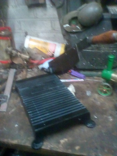
Got the grid lines on the photo cutter. Following the original indents on the frame.
The lines are better in real life, but it doesn't look like it here.
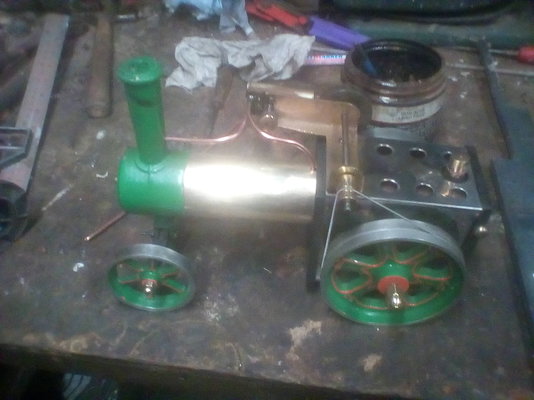
Steam exhaust pipe added and soldered on.
Drive band added and yes it does "chuff" nicely.
But adding a whistle/safety valve is not going to be added.
it will remove the original look of the engine.
Bit of time after work and between food.

Got the grid lines on the photo cutter. Following the original indents on the frame.
The lines are better in real life, but it doesn't look like it here.

Steam exhaust pipe added and soldered on.
Drive band added and yes it does "chuff" nicely.
But adding a whistle/safety valve is not going to be added.
it will remove the original look of the engine.
Aff
Member
- Messages
- 219
- Location
- Weymouth
When I saw Kris's video I thought this may have been you. I was going to come and ask.
Well done. Very nice job.

Kram
Member
- Messages
- 7,417
- Location
- Sussex

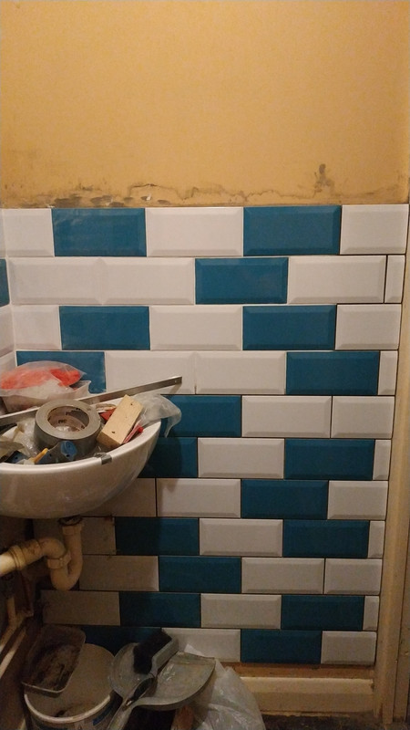
Most of the tiling done!
The under sink, I measured 5 rows dow , screwed a aluminuim bar and worked back up, and then 2 more rows, I was expecting a problem or two, but they all fit almost perfectly. I am impressed with the poundland ruler and wilko level.
"Until I start on the floor tiles which is also the hall way.
selectedgrub
Member
- Messages
- 3,346
- Location
- New Zealand
View attachment 256320 A quick fire grate for an old ,now unobtainable QUEBB wood burner.
Very nice
Johnnybravo
Member
- Messages
- 3,639
- Location
- Northiam
That pattern in the tiles not being symmetrical, would do my head in

Most of the tiling done!
The under sink, I measured 5 rows dow , screwed a aluminuim bar and worked back up, and then 2 more rows, I was expecting a problem or two, but they all fit almost perfectly. I am impressed with the poundland ruler and wilko level.
"Until I start on the floor tiles which is also the hall way.


Last weekends project. I acquired a PZ hay rake and it took a while to collect with lock downs and all so my wife took the truck and collected it when she went to the mother in laws. They are PTO driven and there are spring tines that throw out against a return spring to throw the hay around. We usually use contractors, but borrowed one last year for some small paddocks. Since we are a small farm by modern standards, the contractors don't want to come and do our hay when they can spend days on a big place. I thought it was worth a punt to have one for the odd job.
The seller wasn't quite honest about it's condition or model and the claim it had been used recently (ish) might have been a bit exaggerated. Now for $NZ350 (around 175 quid) I didn't expect much, but it was marginal to fix.
It was supposed to be the PZ300 model, but is the much older PZ200 model, which Google tells me was known for being a bit fragile and not farmer proof, and makes it probably 1970s vintage. This one is a testament to that with plenty of farmer welding and some rough looking braces, and missing a divider that hangs down underneath. It had also been outside for a long, long time judging by the layer of rust that came off when I hit it with a wire brush. Half the tines were missing and some of the return springs were broken. The divider is missing that hangs down below and one of the wheels is broken, although that is my fault as they are horribly balanced and it dropped rather hard on one side. The divider had a huge hit at one stage that sheared off the arm and twisted up the torsion spring that is supposed to stop that happening.
The PTO driveshaft is missing a guard cover ($NZ140) for 'elf n safety, but more importantly it is rusted together instead of sliding nicely so it will shorten up when you lift the hay rake up. If I can't fix that or it is bent, it will be a new $NZ650 - $700 PTO shaft, which will blow the budget to hell.
View attachment 249102View attachment 249103
it should look more like
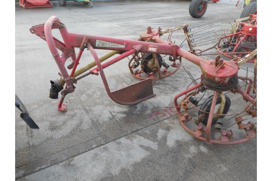
I was tempted to scrap it and write off my gamble, but that would be admitting failure. The bearings seem ok, and it has the remnants of grease within living memory, so I will have to at least double my costs, or three or 4 times if I need a new PTO shaft, and see if it will fix up. If not, I will deny to the wife that I ever had it or find another one and pass it off...
I started taking the broken tines off, and the nuts were rusted solid. Blew them off with the oxy set, since they loosen up when they are molten. I started to wire brush it down. I got a quote for sandblasting and proper painting but at around $NZ800, it was more than I wanted to spend on something that wasn't in great condition.
This weekend if the weather is good is to get some rust killer on it and maybe some paint, and drop the wheels off so I can see if I can fit a new wheel. I have ordered new tines and springs.
It was supposed to be an easy job
The hay rake got put on the back burner with the occaisional burst of enthusiasm until it rains again, but last weekend I got around to making the missing swathe divider - the hockey stick shaped thing in the middle. I had been waiting for a spring from Aliexpress, and when it arrived I realised I had ordered the wrong size. 2 months waiting...
The original is 40mm tube for the divider but this one was missing. It had a big hit at some stage and sheared off. There is a spring made of 4 strips of steel inside the tube fixed at one end so in theory it can move. This one moved alright-
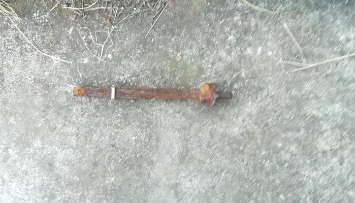
It was bent over 90 degrees. worse the tube remains were inside and well rusted in. In the end I used a piece of 25mm water pipe (32m OD) that was snug fit into the remaining tube and made the rest.
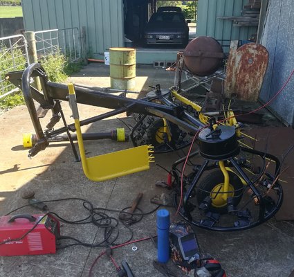
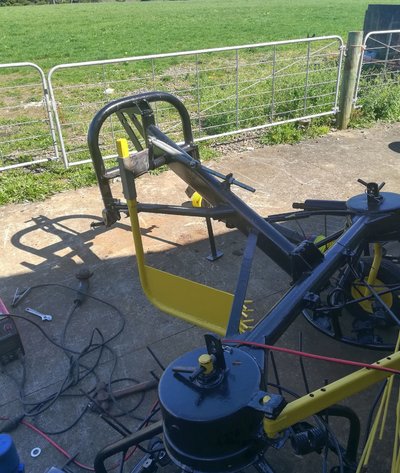
As I wasn't sure what height it needs to be, I made it adjustable. 2 trampoline springs pull it back into place. They are to light and I will probably need to find some heavier ones. We have some silage to cut soon, so I will experiment with it as is then decide if I need to buy another spring. It looks a bit hokey, but I need to get it away from the workshop for the next project.
The paint hides many sins...
At least if it runs, I can get my money and materials back, and it should be useful for turning small paddocks.
wyn
Member
- Messages
- 3,682
- Location
- Cardiff
The hay rake got put on the back burner with the occaisional burst of enthusiasm until it rains again, but last weekend I got around to making the missing swathe divider - the hockey stick shaped thing in the middle. I had been waiting for a spring from Aliexpress, and when it arrived I realised I had ordered the wrong size. 2 months waiting...
The original is 40mm tube for the divider but this one was missing. It had a big hit at some stage and sheared off. There is a spring made of 4 strips of steel inside the tube fixed at one end so in theory it can move. This one moved alright-
Looks good.
Have you had to change a broken tine return spring yet................it takes a bit of working out how to do it.........i've heard of someone who spent half a day trying to change 1 spring.


