You are using an out of date browser. It may not display this or other websites correctly.
You should upgrade or use an alternative browser.
You should upgrade or use an alternative browser.
Stuff you have made today
- Thread starter God mode restorations
- Start date
8ob
Member
- Messages
- 13,976
- Location
- Nescient in the vale
All I'm going to say, is you can have have too much torque. A lightweight car that simply lights its tyres up when you apply a mm of throttle is funny the first 60 seconds . . and absolutely useless ever after. Seven style cars thrive on revs and handling from a low polar moment of inertia. Confuse that by overloading it with torque, and power, and granny on her way to the shops with an open tray of eggs on the passenger seat in her 1.2 Fiesta will humiliate you around roundabouts, or in anything other than bone dry conditions.
Admittedly her Fiesta won't sound as nice
Engine with gearbox has been on a big diet and is a lot lighter than most of the popular four pots, its also mounted a lot lower and a lot further back than with a normal four pot install. Engine is being built as a 7500rpm dry sumped screamer as opposed to a torque monster so it should all work out well, certainly wont get embarrassed in the twisty bits, a mate had a V8 westfield and that thing certainly never had traction,stopping or turning problems, this thing I am building should be an improvement on that.
Bob
Brad93
Member
- Messages
- 18,619
- Location
- Essex, United Kingdom
Wh

Where is your ce mark

Munkul
Jack of some trades, Master of none
- Messages
- 7,648
- Location
- Cumbria
I'm working for someone elseWh
Where is your ce mark

Brad93
Member
- Messages
- 18,619
- Location
- Essex, United Kingdom
Made in your workshop, doesn’t matter.I'm working for someone else
Munkul
Jack of some trades, Master of none
- Messages
- 7,648
- Location
- Cumbria
Their problem, not mine. I'm selling labour, not steel.Made in your workshop, doesn’t matter.
Nice resto, also nice head on the beer.This £5 vice was a fun restoration and showed the New MIS members that something that looked like it was well past the saving stage can be brought back to life.
View attachment 295234
A nice, but in a poor state.
Seized.
Broken.
Missing parts.
Badly rusted and pitted.
View attachment 295235
The screw thread nut was broken.
View attachment 295236
The front of the fixed jaw was also broken. But did allow easier access the pull the nail out holding the spring.
To open remove the moving jaw. Soak well oil, warm the fixed jaw up as much as you can.
Then drive in shaped wooden wedges between the fixed and moving jaw.
Drive home and walk away.
The forces and the drew will start the jaws moving.
View attachment 295237
The Nut was brazed up to repair it.
That is not another crack on the RHS, just a casting mark.
View attachment 295238
Replacement jaw made from scrap bar. Hand drilled.
Then case hardened.
Crush some hard wood charcoal into powder, heat the bar to red heat and cover in the powder.
View attachment 295240
All 4 jaw screw holes were striped. 2 before I got the vice. The last 2 by me when removing them.
So they are drilled and taped to M10, the suds are then filled flat and drilled and taped to M6.
View attachment 295241
On the final leg.
View attachment 295242
Down side of gold leaf.
It will show up any flaws.
Oh well.
View attachment 295243

Dr.Al
Forum Supporter
- Messages
- 2,369
- Location
- Gloucestershire, UK
I got fed up with the fact that every time I googled for "gear calculator" to remind myself of the equations for involute gears, most of the resulting links seem to be stuck in the dark ages of diametral pitch and inches. Rather than doing something sensible like keeping on searching and then bookmarking one that used the module system, I made my own (it also generates DXFs or SVGs of the gear profile).
Link: https://www.cgtk.co.uk/metalwork/calculators/gears
Screenshot:

Link: https://www.cgtk.co.uk/metalwork/calculators/gears
Screenshot:
James1979
Member
- Messages
- 8,434
- Location
- Orkney
Thank youI got fed up with the fact that every time I googled for "gear calculator" to remind myself of the equations for involute gears, most of the resulting links seem to be stuck in the dark ages of diametral pitch and inches. Rather than doing something sensible like keeping on searching and then bookmarking one that used the module system, I made my own (it also generates DXFs or SVGs of the gear profile).
Link: https://www.cgtk.co.uk/metalwork/calculators/gears
Screenshot:
View attachment 295318
That will be very useful
If you ever write one for bike sprockets it’s would also be handy
 I’ve often wondered what a plasma one would be like vs a shop bought one. Obviously you’d have to profile it a bit on the lathe but a few afternoons at the mx track buggers them so the ability to cut my own would be damn handy.
Brad93
Member
- Messages
- 18,619
- Location
- Essex, United Kingdom
Another bookmark to your site addedI got fed up with the fact that every time I googled for "gear calculator" to remind myself of the equations for involute gears, most of the resulting links seem to be stuck in the dark ages of diametral pitch and inches. Rather than doing something sensible like keeping on searching and then bookmarking one that used the module system, I made my own (it also generates DXFs or SVGs of the gear profile).
Link: https://www.cgtk.co.uk/metalwork/calculators/gears
Screenshot:
View attachment 295318
Dr.Al
Forum Supporter
- Messages
- 2,369
- Location
- Gloucestershire, UK
Another bookmark to your site added
Do let me know if you spot any mistakes!
Agroshield
Member
- Messages
- 5,655
Screenshot:
There is little point in going to splines. If someone is going to use the dxf for cutting a gear on a CNC machine, the G-code that the machine accepts only understands straight lines and circular arcs. So whatever mathematical representation of the involute you use, it will be converted to one of those in the CAM.
A very good addition to the program would be the ability to produce a dxf of a pitch-shifted gear, so you can alter centres or have different size gears meshing on the same centres (this is how the Gamet dual dials work - a 125 and 127 internal gear, but cut on the same pitch circle. It can also be used to make a metric thread dial easier to use; a 35t and 36t gear cut on the same pitch circle). Look on khkgears site for info. on pitch shifting, and being Japanese, they use metric units so your blood pressure will remain steady.
Thank you
That will be very useful
If you ever write one for bike sprockets it’s would also be handyI’ve often wondered what a plasma one would be like vs a shop bought one. Obviously you’d have to profile it a bit on the lathe but a few afternoons at the mx track buggers them so the ability to cut my own would be damn handy.
Are you aware of the document here: https://gizmology.net/sprockets.htm that shows you how do draw one in CAD. See also: https://sprocketeer.software.informer.com/2.0/
James1979
Member
- Messages
- 8,434
- Location
- Orkney
I was not but I am now thank you very much.There is little point in going to splines. If someone is going to use the dxf for cutting a gear on a CNC machine, the G-code that the machine accepts only understands straight lines and circular arcs. So whatever mathematical representation of the involute you use, it will be converted to one of those in the CAM.
A very good addition to the program would be the ability to produce a dxf of a pitch-shifted gear, so you can alter centres or have different size gears meshing on the same centres (this is how the Gamet dual dials work - a 125 and 127 internal gear, but cut on the same pitch circle. It can also be used to make a metric thread dial easier to use; a 35t and 36t gear cut on the same pitch circle). Look on khkgears site for info. on pitch shifting, and being Japanese, they use metric units so your blood pressure will remain steady.
Are you aware of the document here: https://gizmology.net/sprockets.htm that shows you how do draw one in CAD. See also: https://sprocketeer.software.informer.com/2.0/
Dr.Al
Forum Supporter
- Messages
- 2,369
- Location
- Gloucestershire, UK
There is little point in going to splines. If someone is going to use the dxf for cutting a gear on a CNC machine, the G-code that the machine accepts only understands straight lines and circular arcs. So whatever mathematical representation of the involute you use, it will be converted to one of those in the CAM.
If I'm completely honest, the desire for splines is more about getting a slightly prettier 3D model. I really hope no-one uses my generated DXFs to drive CAM (or at least I hope they don't blame me if it's wrong!). When you extrude a polyline from a DXF into a 3D object (at least in the two CAD applications I tested), you end up with lines along the extrude at each point on the polyline; a spline would remove those lines.
A very good addition to the program would be the ability to produce a dxf of a pitch-shifted gear, so you can alter centres or have different size gears meshing on the same centres (this is how the Gamet dual dials work - a 125 and 127 internal gear, but cut on the same pitch circle. It can also be used to make a metric thread dial easier to use; a 35t and 36t gear cut on the same pitch circle).
Look on khkgears site for info. on pitch shifting, and being Japanese, they use metric units so your blood pressure will remain steady.
Isn't "pitch shifting" the same thing as "profile shifting" (which is already supported). If not, I obviously need to do more reading!
Onoff
In the land of the unfinished project I am King!
- Messages
- 12,059
- Location
- Sevenoaks, UK
Ready for the next one once the copper pipe has stuck to the cross members. Cleaned the mould out and re-siliconed the internal corners:
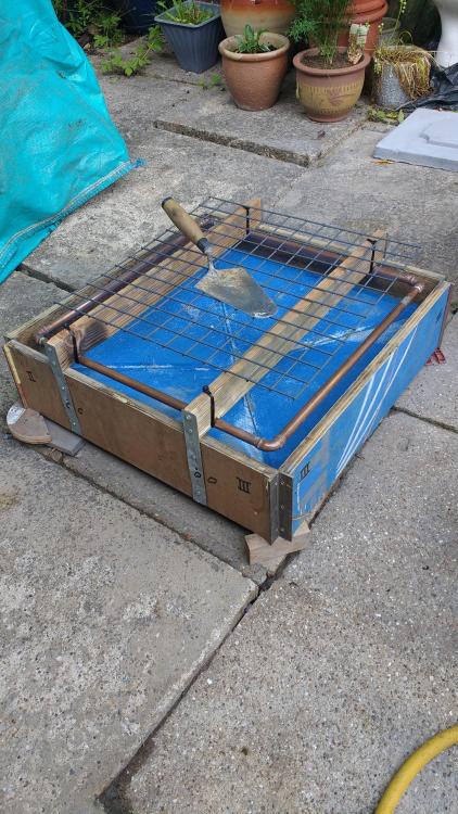
Found a bit of slightly bigger mesh than before, not galvanised, so gave it a quick coat of zinc spray.
Sand and dye already in the mixer:
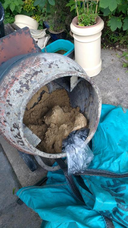
Cement and lime measured out ready.

Found a bit of slightly bigger mesh than before, not galvanised, so gave it a quick coat of zinc spray.
Sand and dye already in the mixer:

Cement and lime measured out ready.
selectedgrub
Member
- Messages
- 3,346
- Location
- New Zealand
The start of some R2D2 legs 


DennisCA
Member
- Messages
- 1,983
- Location
- Finland
Rebuilt my forge, no longer has a chimney. I found that coke smokes so little, not at all really, that I don't need it for outdoor forgning. The earlier design prevented access from all sides as well. Now I can put in a long piece of stock easily.


What it looked like before:


What it looked like before:

Last edited:
Onoff
In the land of the unfinished project I am King!
- Messages
- 12,059
- Location
- Sevenoaks, UK
Second one done. Used the orbital sander against the sides to vibrate it down this time.

Typically I did only 75% of last time's mix (when I had too much left over) and this time was a bit short! Scraped to the sides and filled the hollow in the middle with a nom. 4:1 mix, no lime, no dye, just whatever it picked up from the drum. Was a bit sloppy tbh. Fingers crossed!
Typically I did only 75% of last time's mix (when I had too much left over) and this time was a bit short! Scraped to the sides and filled the hollow in the middle with a nom. 4:1 mix, no lime, no dye, just whatever it picked up from the drum. Was a bit sloppy tbh. Fingers crossed!


