SIP Migmate - Replacing the Wire Liner
This page describes why the wire liner might need to be replaced and how to replace it. I bought a "torch service kit" for about £23 which includes some other bits and pieces, but wire liners are available by themselves for less than £10.
There are recognised weaknesses in the hobby SIP wire feed mechanisms (and those of some other hobby MIG welders). The bottom of the page links to fixes developed by the forum.
The SIP Migmate shares it's wire feed system with the Topmig, and it's common from the 105 amp model up through the 150 and 170 amp welders. This one is a 130 Turbo built around 1998. All seem to have wire feed trouble as the welder gets older and the symptoms are commonly reported on the forum:
- Tricky to get a smooth weld at low amps
- End of wire isn't steady when welding - seems to move up and down
- Motor speed changes while welding
- The wire slips between the feed wheels
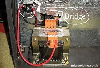
The wire feed motor (circled in red) is one source of the trouble. This is a low cost welder so they made the wire feed motor very small.
It seems to work well enough when new, but doesn't have much extra capacity to overcome problems with the wire feed system and liner as the welder gets older.
High friction
The wire seemed very stiff to pull through the liner.
In the photo I've attached a 1kg (2.2lbs) bag of rice to the end of the wire, removed the tension on the wire feed rollers and the wire reel so the only resistance was in the wire liner and torch, and then tried to lift the rice bag up with the wire.
It took 3.3kg before the wire started to move through the liner. That's more than 3 bags of rice! After the liner was replaced the wire would feed with just 0.6kg weight (just over half a bag of rice).
Replacing the wire liner
Wire liners are available by themselves or as part of a torch service kit which includes a new swan neck, a swan neck liner, and a bunch of spare tips and shrouds.
The torch comes apart with 4 screws. Inside this one there is a brass block that switches the flow of shielding gas (many other welders have an electrical solenoid inside the machine to switch the gas).
I removed the gas pipe connector from the brass block for better access. It was a quick release type where the pipe comes out easily after pushing the sprung outside of the connector inwards towards the brass block.
The brass block was then easy to unscrew from the wire liner, and this also released the power cable.
The welder end is a little more fiddly The wire rollers can be moved away for access. The bottom is held on by 2 screws and the top one will move out of the way when the tensioning bolt is fully unscrewed and the tensioning spring pulled outwards from the welder.
In the photo the spanner is on the brass adaptor that holds the wire liner to the welder.
The brass ends will unscrew from the plastic liner and can be screwed onto a replacement liner. The thread pitch is good for steel liners as well as the original plastic type.
Use a steel liner!
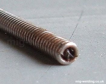
Here's the real trick for rejuvenating an old SIP. The original liner was PVC (top of photo), but the alternative steel liners offer much less resistance to the wire.
The steel liner is stiffer than the plastic liner so helps keep the cord to the torch straight, again reducing friction for the wire.
The steel liners can be colour coded. Blue is for 0.6mm - 0.9mm wire and red for 1.0mm - 1.2mm. Steel liners might not be available for all hobby machines, and eurotorch liners won't fit.
The replacement liner pushes in from the torch end. They are often too long and need to be trimmed. An angle grinder can make a reasonably clean cut, but any sharp edges need to be cleaned off with a small file or drill bit. I'm told that side cutters might have been more sensible.
I cut mine to the same length as the old one, but a more sensible approach might have been to insert the liner, screw in in place at the torch end, pull the lead straight, then mark the correct length at the welder end. If the liner is too long it might put strain on the power lead connection (which isn't all that robust).
The gap between the end of the liner and the rollers should be as small as possible otherwise unsupported wire could birds nest (crumple up) before it makes it into the liner.
The power cable and cord cover are secured to the end of the wire feed mechanism with a wiring tie. I've routed the gas line around the wiring tie to prevent it from being squashed. I assume this is what SIP would have done originally, but my welder is old and messed around with so I can't be sure.
Swan neck
The swan neck won't normally need to be replaced unless the screw thread for the tip is damaged, but it's a quick and easy job. The neck is clamped into the brass block with a grub screw.
The thing that does need to be replaced on this welder is the swan neck liner (in the photo the replacement is being pushed through the swan neck). It's always worth fitting a contact tip to check the length of this liner before screwing everything back together. Mine was a bit long and needed to be trimmed.
Here's a blurry photo of the end of the old swan neck liner. It's full of bits of plastic pulled out of the old PVC wire liner. I guess the bits of plastic worn off the liner make it as far as the tip, get hot, then melt together. Can't be the best thing for a smooth wire feed.

Setting the tensioners
First the wire roller with the grove needed to be cleaned out - the groove was full of black gunk. From there I set the wire reel on a reasonably loose tension (the reel tensioner on this welder doesn't seem to make much difference anyway).
The roller tension adjuster worked well screwed 3/4 of the way in. Much better than the original setting where it needed to be screwed in all the way and then a bit more. I set it so that it would push against a reasonable resistance but slip if the wire became jammed in the tip. I'm running a partly used 5kg reel of wire. A smaller reel would put less strain on the wire feed mechanism.
For more detail see setting up the wire feed.
The verdict
With everything back together the welder was transformed. The end of the wire is now much more stable when welding, hence the arc is less stuttery and the welder is easier to fine tune.
It is still a tricky welder to set up and use. The wire speed control is sensitive and unforgiving if the speed is slightly out. I did find neat welds more difficult to achieve then with more expensive welders, but for occasional work the welder is now usable.
The test welds on the picture are continuous welds on 0.8mm sheet on minimum power and using Argon/CO2 mix gas and 0.6mm wire. The welds aren't perfect, but welding at this thickness was almost unachievable before the liner was replaced.
How often should the liner be replaced?
The professionals on the forum tend to replace their wire liners after running through 30kg of wire. At their rate of use that can be once a month. A hobby welder might not get through 30kg of wire in it's lifetime. For hobby welders the main cause of liner wear is wire that has a light coating of rust due to infrequent use. Rust is an abrasive, and the liner might need to be replaced after just a few minutes of welding with rusty wire. (Rusty wire should really be unwound and cut from the reel before welding).
Steel vs plastic liners
The plastic liner originally fitted to this SIP welder had recently been replaced but was still causing wire feed problems. The wire feed system on this welder seems to be very marginal, and the plastic liner pushes it over the edge. The steel liner offers only 20% of the resistance of the old plastic liner and the welder works much more predictably with the new steel liner.
Still not working? - Align the rollers
The pivot for the top roller is mounted only on one side. The pivot can flex causing the top roller to contact the bottom on one edge rather than gripping the wire. An excellent solution suggested on the forum is to add a second support for the top roller to prevent twisting. See the SIP / Cosmo Wire Feed Solution thread for details.
Modifications
The wire feed stability on hobby SIP welders can be poor, and forum members have found supplying the wire feed with a dedicated power supply can improve stability.
The forum Super SIP is under development. Here's Bump's page on fitting an additional transformer to provide a stable voltage to the wire feed motor. That post has much of the information, but BChild's installation is much neater (page 6 for the photos, but the rest is also worth a read). The most effective modification I have tested is the alternative modification using a switching power supply from BillJ.


