Dr.Al
Forum Supporter
- Messages
- 2,507
- Location
- Gloucestershire, UK
In the last post, I talked about a simpler version of the control cabinet schematic. Let's go back to the more complicated version that has become possible thanks to my generous benefactor!
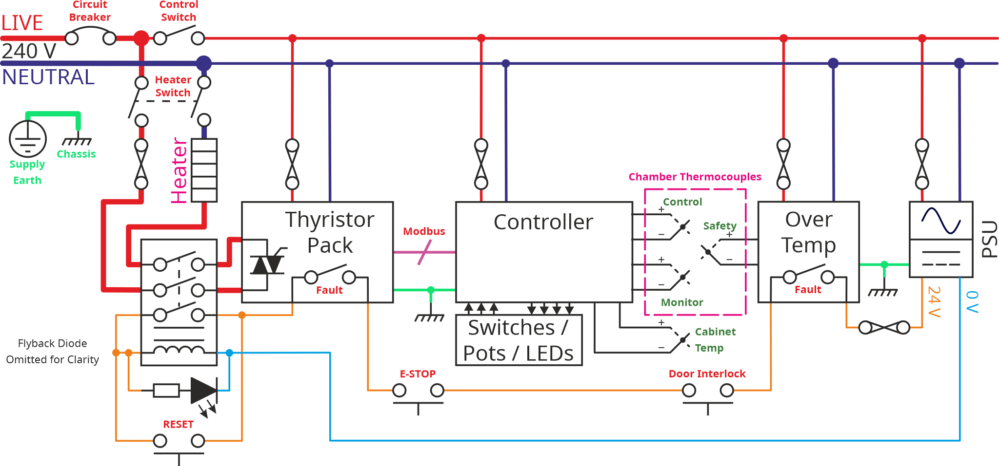
The control part of this schematic is certainly more complex, but there aren't that many components involved. Starting on the right (and ignoring the power supply that I've already discussed), there's a simple over temperature monitor. This over temperature monitor (an Omron E5C2) has a simple dial on the front allowing you to set a threshold temperature of anything up to 1200°C. If the temperature goes above that threshold, it opens a switch (in the safety circuit) which will cause the contactor to open and hence the power will be disconnected. That's used as a safety device in case of any faults in the other parts of the system.
To the left of that over temperature device, there are a handful of thermocouples. One is used for the over temperature trip, one is connected to the controller to control the chamber temperature. The other two are there purely because the fancy "Eurotherm Nanodac" controller I'm using has lots of input channels, so I thought it would be interesting to try logging temperature in a couple of different places and seeing how it varies.
Next to the left is the Nanodac controller. This is a very fancy device with a big screen and lots of input/output connections. I'll be discussing the controller more in due course, but for now it can be thought of as the same as the simple PID controller I discussed before: it reads the temperature, then tries to drive the heater coil (via the thyristor pack) to get the temperature to the right level.
There are some switches, lights and pots (potentiometers: variable resistors in the form of a rotating knob that can be used to adjust something). Exactly what they'll be used for is yet to be determined.
The thyristor pack is the thing that controls the actual current through the heater. It's a very fancy one (called a Eurotherm EPack). I doubt I'll use many of its features, but the ability to run at a reduced current is definitely of interest.
The controller and the thyristor pack "talk to each other" via a Modbus TCP interface. I've never used Modbus TCP before, but I have used its serial equivalent, Modbus RTU. It's essentially a way for control equipment to send commands to other control equipment over an ethernet cable. From the point of view of the user (i.e. me), it's very simple: you plug the two devices together and then tell one of them what address to write to in the other; Eurotherm have sorted all hard work of making them talk.
Over the Christmas break we'd arranged five nights in Lyme Regis with various family members congregating on two cottages in that beautiful town. I was fairly sure there would be a fair amount of "down-time" during the week, so I wanted to use that time to do some investigation into the fancy control gear. That thought led to yet another wiring diagram:
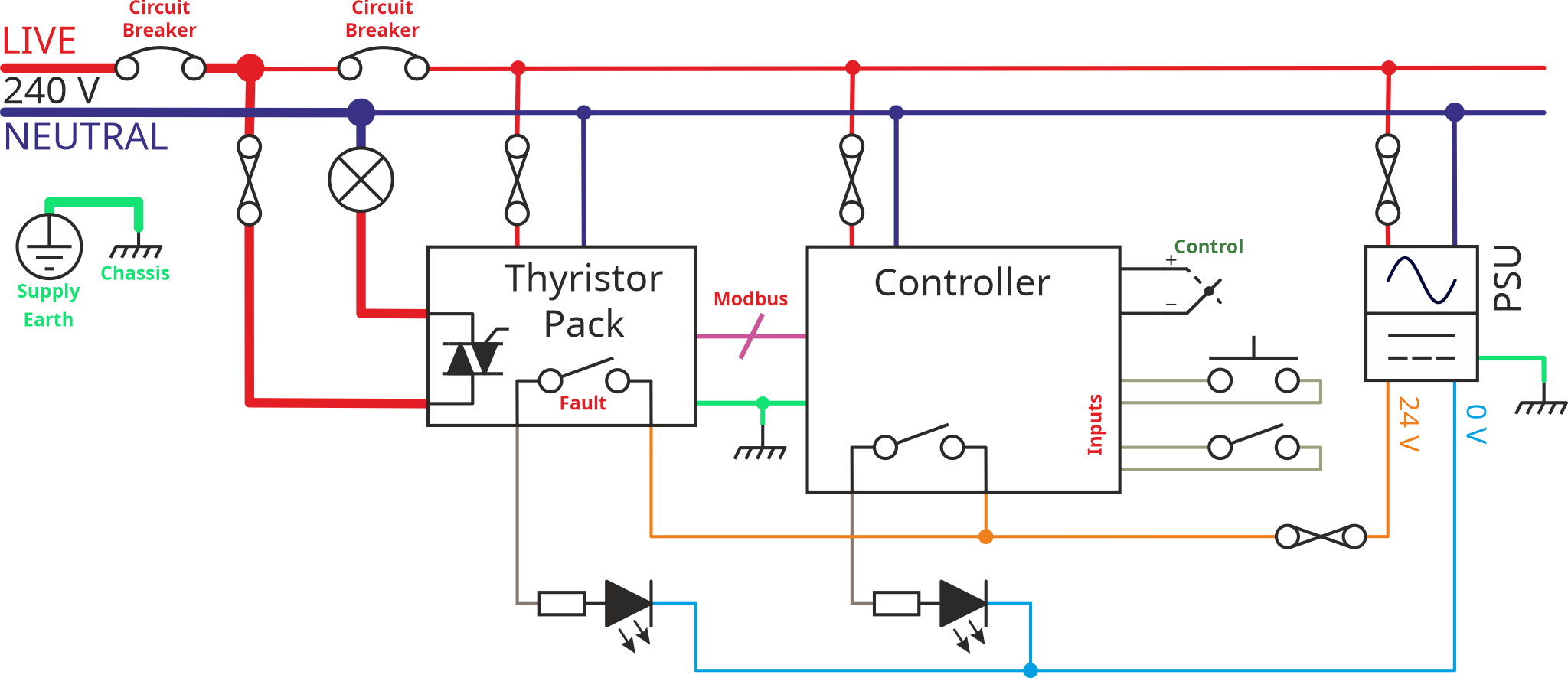
This one is again very similar to previous versions, but most of it has been removed. The controller still talks Modbus to the thyristor pack, but the thyristor pack is now just driving a light bulb (shown as a circle with a cross through it). The fault output from the thyristor goes to an LED, as does one of the outputs from the controller. There are a couple of switches and a thermocouple going to controller inputs.
I set the 3D-printer going making a few mounting frames and then spent an inordinate amount of time wiring it up (for such a simple schematic you'd think it would be a quick job!)
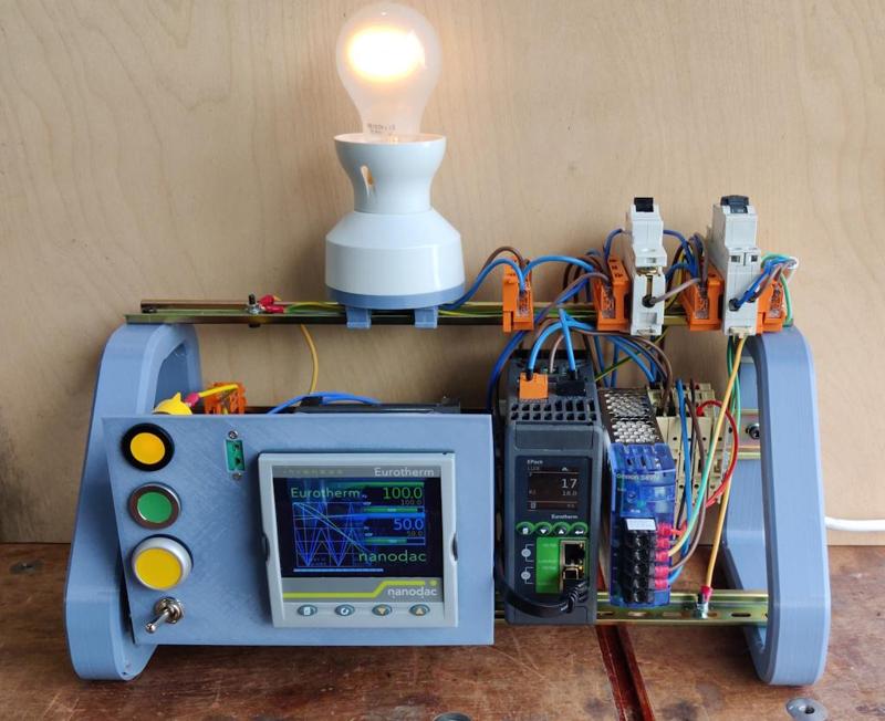
This is what it looked like when finished (the controller and thyristor pack both had configurations pre-installed by my generous benefactor as he'd tested them both using a similar set-up):
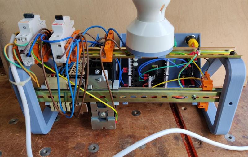
It looks like more of a rats-nest on the back:
This close-up shot shows that big display on the fancy controller (when the photo was taken it was still in the process of booting up, which takes a little while):
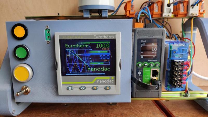
To the left of the controller are a pair of panel-mounted LEDs (one yellow, one green), a yellow push-button and a toggle switch. There's also a socket into which a thermocouple can be plugged. To the right of the controller are the thyristor pack and a power supply.
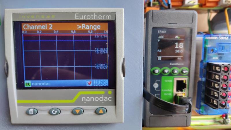
This photo shows what the controller looks like after it has booted up. It has several different options for what's shown on the screen; this was just what came up by default.
Over the course of the time in Lyme Regis, I managed (after getting over quite a few hurdles) to get the controller and thyristor pack at least partly tamed. The first thing I did was a very simple configuration that turned the green LED on and off according to the position of the toggle switch. Not exactly earth-shattering, but getting there required gaining quite a bit of understanding of the Eurotherm iTools software that is used to configure both devices.
After that, I made another simple configuration that set the output power (i.e. the brightness of the bulb) to a level proportional to the temperature of a thermocouple plugged into the socket. With that configuration, I could grab hold of the end of the thermocouple (thereby heating it) and the light would get brighter. Releasing the thermocouple would cause the light to dim.
This is what those configurations looked like in iTools for the Nanodac controller (there's much more to it but I thought I'd share an overview):
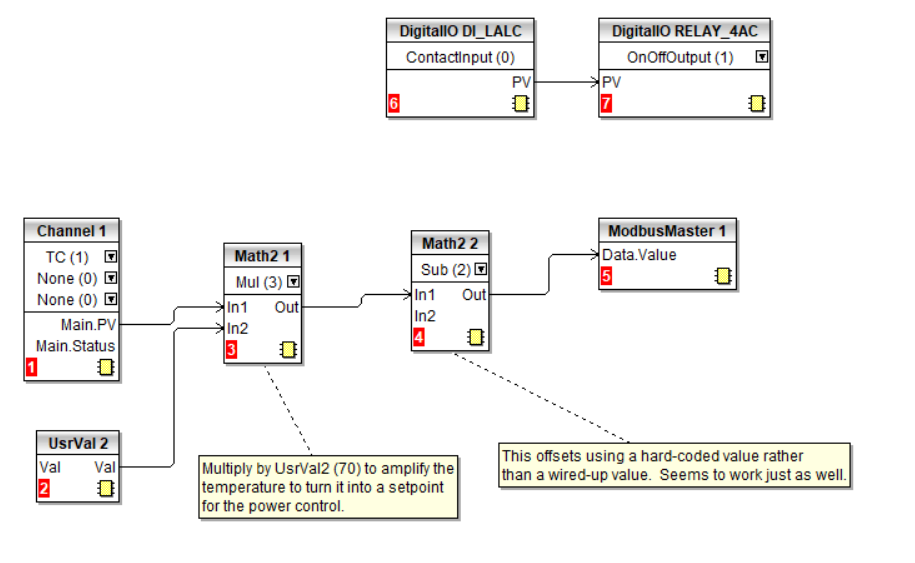
The top half of that circuit just connects one of the inputs to one of the outputs. With the way I wired it up, that made the switch state affect the LED state: flipping the switch made the LED turn on or off.
The bottom half takes the measurement from the thermocouple (wired into Channel 1) and does some simple maths on it (multiplies it by 70 and then subtracts 1400) and then writes it (via Modbus) to the thyristor pack. The numbers used in the maths blocks were chosen fairly arbitrarily, but they result in a temperature range of 20°C to 35°C mapping to an output value of 0 to 1050. That lined up with what seemed to be the expected range of values from fully off to fully on for the thyristor pack. I'm still learning how the thyristor pack works so I don't think I can fully explain that bit yet!
That's it for now. I think that setting up the controller and thyristor pack is going to end up being the most time-consuming part of this project, but I'm quite enjoying playing with it and learning how it all works (and my generous benefactor has continued to be helpful by providing lots of support!) so I don't mind that at all. All being well, I'll be able to make the controller do some extra interesting things (beyond "simply" controlling the oven temperature).
I'm back home now and I'd like to start making some progress on the physical build of the chamber and the control cabinet, so the next post (or several) will probably be back to my normal style of build write-up.

The control part of this schematic is certainly more complex, but there aren't that many components involved. Starting on the right (and ignoring the power supply that I've already discussed), there's a simple over temperature monitor. This over temperature monitor (an Omron E5C2) has a simple dial on the front allowing you to set a threshold temperature of anything up to 1200°C. If the temperature goes above that threshold, it opens a switch (in the safety circuit) which will cause the contactor to open and hence the power will be disconnected. That's used as a safety device in case of any faults in the other parts of the system.
To the left of that over temperature device, there are a handful of thermocouples. One is used for the over temperature trip, one is connected to the controller to control the chamber temperature. The other two are there purely because the fancy "Eurotherm Nanodac" controller I'm using has lots of input channels, so I thought it would be interesting to try logging temperature in a couple of different places and seeing how it varies.
Next to the left is the Nanodac controller. This is a very fancy device with a big screen and lots of input/output connections. I'll be discussing the controller more in due course, but for now it can be thought of as the same as the simple PID controller I discussed before: it reads the temperature, then tries to drive the heater coil (via the thyristor pack) to get the temperature to the right level.
There are some switches, lights and pots (potentiometers: variable resistors in the form of a rotating knob that can be used to adjust something). Exactly what they'll be used for is yet to be determined.
The thyristor pack is the thing that controls the actual current through the heater. It's a very fancy one (called a Eurotherm EPack). I doubt I'll use many of its features, but the ability to run at a reduced current is definitely of interest.
The controller and the thyristor pack "talk to each other" via a Modbus TCP interface. I've never used Modbus TCP before, but I have used its serial equivalent, Modbus RTU. It's essentially a way for control equipment to send commands to other control equipment over an ethernet cable. From the point of view of the user (i.e. me), it's very simple: you plug the two devices together and then tell one of them what address to write to in the other; Eurotherm have sorted all hard work of making them talk.
Over the Christmas break we'd arranged five nights in Lyme Regis with various family members congregating on two cottages in that beautiful town. I was fairly sure there would be a fair amount of "down-time" during the week, so I wanted to use that time to do some investigation into the fancy control gear. That thought led to yet another wiring diagram:

This one is again very similar to previous versions, but most of it has been removed. The controller still talks Modbus to the thyristor pack, but the thyristor pack is now just driving a light bulb (shown as a circle with a cross through it). The fault output from the thyristor goes to an LED, as does one of the outputs from the controller. There are a couple of switches and a thermocouple going to controller inputs.
I set the 3D-printer going making a few mounting frames and then spent an inordinate amount of time wiring it up (for such a simple schematic you'd think it would be a quick job!)
This is what it looked like when finished (the controller and thyristor pack both had configurations pre-installed by my generous benefactor as he'd tested them both using a similar set-up):

It looks like more of a rats-nest on the back:

This close-up shot shows that big display on the fancy controller (when the photo was taken it was still in the process of booting up, which takes a little while):

To the left of the controller are a pair of panel-mounted LEDs (one yellow, one green), a yellow push-button and a toggle switch. There's also a socket into which a thermocouple can be plugged. To the right of the controller are the thyristor pack and a power supply.
This photo shows what the controller looks like after it has booted up. It has several different options for what's shown on the screen; this was just what came up by default.

Over the course of the time in Lyme Regis, I managed (after getting over quite a few hurdles) to get the controller and thyristor pack at least partly tamed. The first thing I did was a very simple configuration that turned the green LED on and off according to the position of the toggle switch. Not exactly earth-shattering, but getting there required gaining quite a bit of understanding of the Eurotherm iTools software that is used to configure both devices.
After that, I made another simple configuration that set the output power (i.e. the brightness of the bulb) to a level proportional to the temperature of a thermocouple plugged into the socket. With that configuration, I could grab hold of the end of the thermocouple (thereby heating it) and the light would get brighter. Releasing the thermocouple would cause the light to dim.
This is what those configurations looked like in iTools for the Nanodac controller (there's much more to it but I thought I'd share an overview):

The top half of that circuit just connects one of the inputs to one of the outputs. With the way I wired it up, that made the switch state affect the LED state: flipping the switch made the LED turn on or off.
The bottom half takes the measurement from the thermocouple (wired into Channel 1) and does some simple maths on it (multiplies it by 70 and then subtracts 1400) and then writes it (via Modbus) to the thyristor pack. The numbers used in the maths blocks were chosen fairly arbitrarily, but they result in a temperature range of 20°C to 35°C mapping to an output value of 0 to 1050. That lined up with what seemed to be the expected range of values from fully off to fully on for the thyristor pack. I'm still learning how the thyristor pack works so I don't think I can fully explain that bit yet!
That's it for now. I think that setting up the controller and thyristor pack is going to end up being the most time-consuming part of this project, but I'm quite enjoying playing with it and learning how it all works (and my generous benefactor has continued to be helpful by providing lots of support!) so I don't mind that at all. All being well, I'll be able to make the controller do some extra interesting things (beyond "simply" controlling the oven temperature).
I'm back home now and I'd like to start making some progress on the physical build of the chamber and the control cabinet, so the next post (or several) will probably be back to my normal style of build write-up.


